
Taurus V6-182 3.0L FF (1995)
Transmission Range Sensor: Description and Operation
Manual Lever Position Sensor
PURPOSE
The Manual Lever Position (MLP) sensor provides an input signal to the Powertrain Control Module (PCM), notifying the PCM of the current
transmission shift lever position.
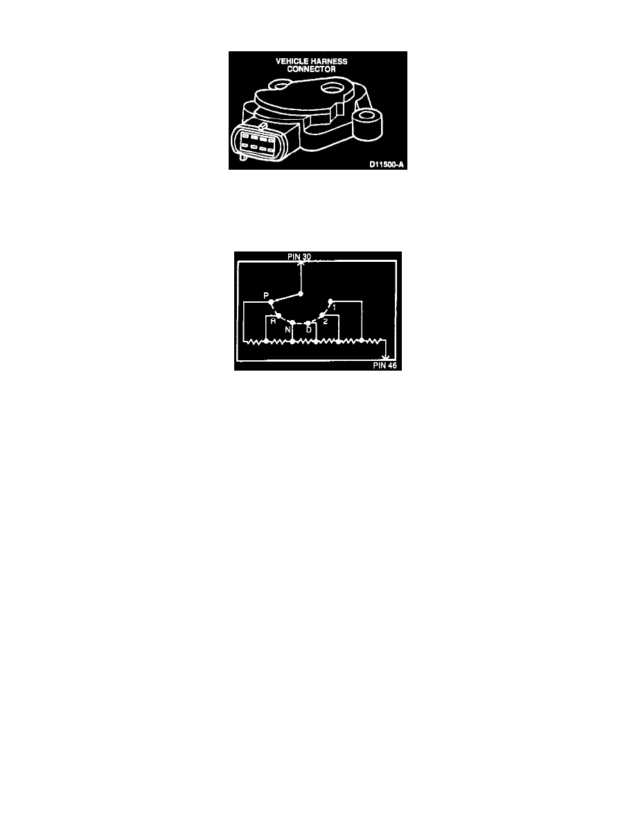
Schematic
CONSTRUCTION
The MLP has six separate resistors in series. Each resistor has an output connection corresponding to a transmission position (P, R, N, D, 1, 2).
The output wiper arm is linked directly to the transmisssion selector linkage.
OPERATION
The PCM applies a 5.0 volt reference signal to the MLP circuit pin 30. SIG RTN circuit pin 46 supplies a ground path to the sensor. As the
transmission is shifted the MLP output wiper arm moves to a corresponding resistor connection. The six inline resistors provide a separate voltage
drop for each transmission position.
RELATED DIAGNOSTIC TROUBLE CODES
DTC 67/634 - The MLP sensor was out of self-test range with the transmission in park.
DTC 522/654 - The gear selector was not in park during the self-test.