
Taurus V6-183 3.0L VIN U FI (1993)
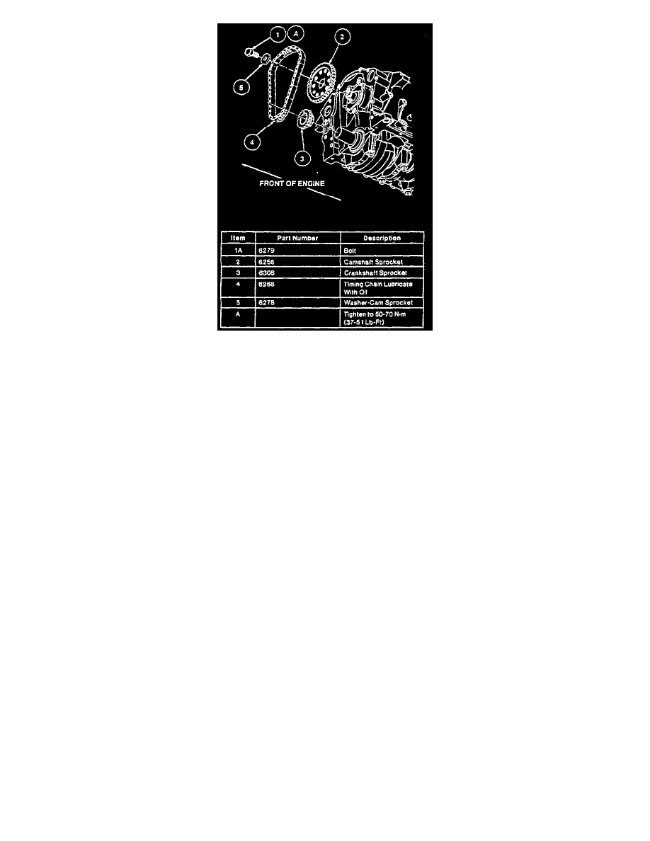
Fig. 9 Timing Chain Installation
1.
Relieve fuel system pressure as outlined under MAINTENANCE PROCEDURES/FUEL SYSTEM PRESSURE RELIEF.
2.
Disconnect battery ground cable, then loosen four water pump pulley bolts with drive belt in place.
3.
Loosen alternator belt-adjuster jackscrew to provide sufficient slack in belt for removal.
4.
Drain cooling system, then remove lower radiator hose and heater hose from water pump.
5.
Remove crankshaft pulley and damper as described in FRONT OIL SEAL.
6.
Drain and remove oil pan as described under OIL PAN.
7.
Remove timing cover to block retaining bolts. Timing cover and water pump may be removed as an assembly by not removing bolts Nos. 11---15
as shown in Fig. 11.
8.
After cover is pulled away from block, remove water pump pulley and bolts.
9.
Rotate crankshaft until No. 1 piston is at TDC and timing marks are aligned, Fig. 8.
10.
Remove camshaft sprocket retaining bolt and washer.
11.
Check timing chain deflection for excessive wear.
12.
Slide sprockets and timing chain forward and remove as an assembly.
13.
Reverse procedure to install, noting the following:
a. Slide timing chain and sprockets on with timing marks aligned, Fig 9.
b. Carefully clean all gasket material from timing cover and cylinder block. The aluminum timing cover gouges easily, use care when
scraping gasket.
c. Inspect timing cover crankshaft seal, replace if necessary.
d. Before installing bolt Nos. 1, 2 and 3, apply pipe sealant No. D6AZ-19558-A or equivalent.
e. Tighten front cover bolts to sequence shown in Fig. 11.
f.
On 1991 models, torque bolts 1 through 10 to 19 ft. lbs., then bolts 11 through 15 to 7 ft. lbs.
g. On 1992---94 models, torque bolts 1 through 10 to 15---22 ft. lbs., then bolts 11 through 15 to 71---106 inch lbs.