
Taurus V6-183 3.0L VIN U FI (1993)
Control Module HVAC: Description and Operation
Electronic Climate Control Module
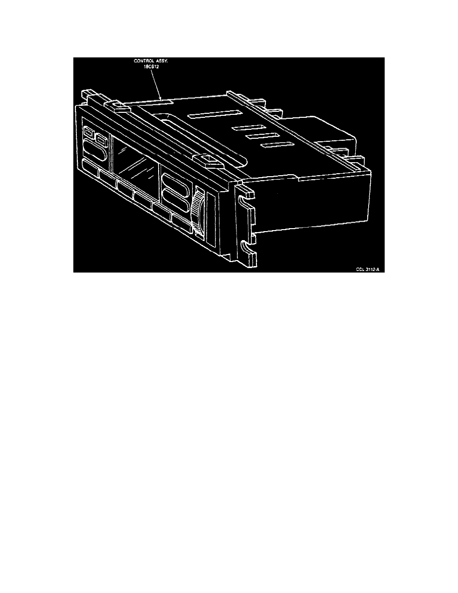
CONTROL ASSEMBLY
Control Assembly
A Self Test feature has been included in the control assembly to supply the technician with air distribution error codes. These codes direct the technician
to the damaged component. The Self Test is described as outlined.
The EATC assembly is located in the instrument panel and consists of 10 push buttons, a variable blower speed control knob for manual input and a
Vacuum Fluorescent Display (VFD) for displaying set temperature, ambient temperature, function, and diagnostic codes.
When the system is operating under AUTOMATIC control, the VFD display will show the preferred or target temperature to which the elements of the
automatic control system respond. Blower motor speed, under automatic control, varies in response to ambient temperature changes and a predetermined
delay factor. Temperature selection may be raised or lowered in one degree increments between 18° C (65° F) and 29° C (85° F) by pressing the red
button to raise or the blue button to lower the desired temperature and the automatic control will respond accordingly.
Other control assembly features include:
^ A 16° C (60° F) setting for maximum cool and a 32° C (90° F) setting for maximum heat.
^ An OUTSIDE TEMP button which, when depressed, will result in a four-second display of the air temperature outside the vehicle.
^ An OFF button which, if depressed, will apply vacuum to close the outside-recirculating air door, shut off blower motor operation, and discontinue
the climate control functions through the system.
When the thumbwheel control for the blower motor is rotated out of the position it occupied under automatic control, it will remain under manual control
until the automatic button is again depressed. Under automatic control, blower speed varies as required to accommodate the total automatic functions in
the system. Under manual control, blower speed is constant based on the thumbwheel setting.
An illumination bulb in the control assembly provides backlighting for the Vacuum Fluorescent Display (VFD) window. When the rheostat on the
headlamp/parking lamp switch is rotated, the intensity of the light from this bulb will increase or decrease depending upon the direction of rotation. (The
backlighting on the control assembly, as well as in other instrument panel locations, will dim whenever the light switch is engaged.)