
Taurus V6-183 3.0L VIN U FI (1993)
Alternator Lamp/Indicator: Testing and Inspection
Motorcraft Integral Alternator Regulator (IAR) System
NOTE: The operations and on vehicle test procedures for the side terminal alternator are same as for rear terminal alternator. However, the internal
wiring and bench test procedures differ.
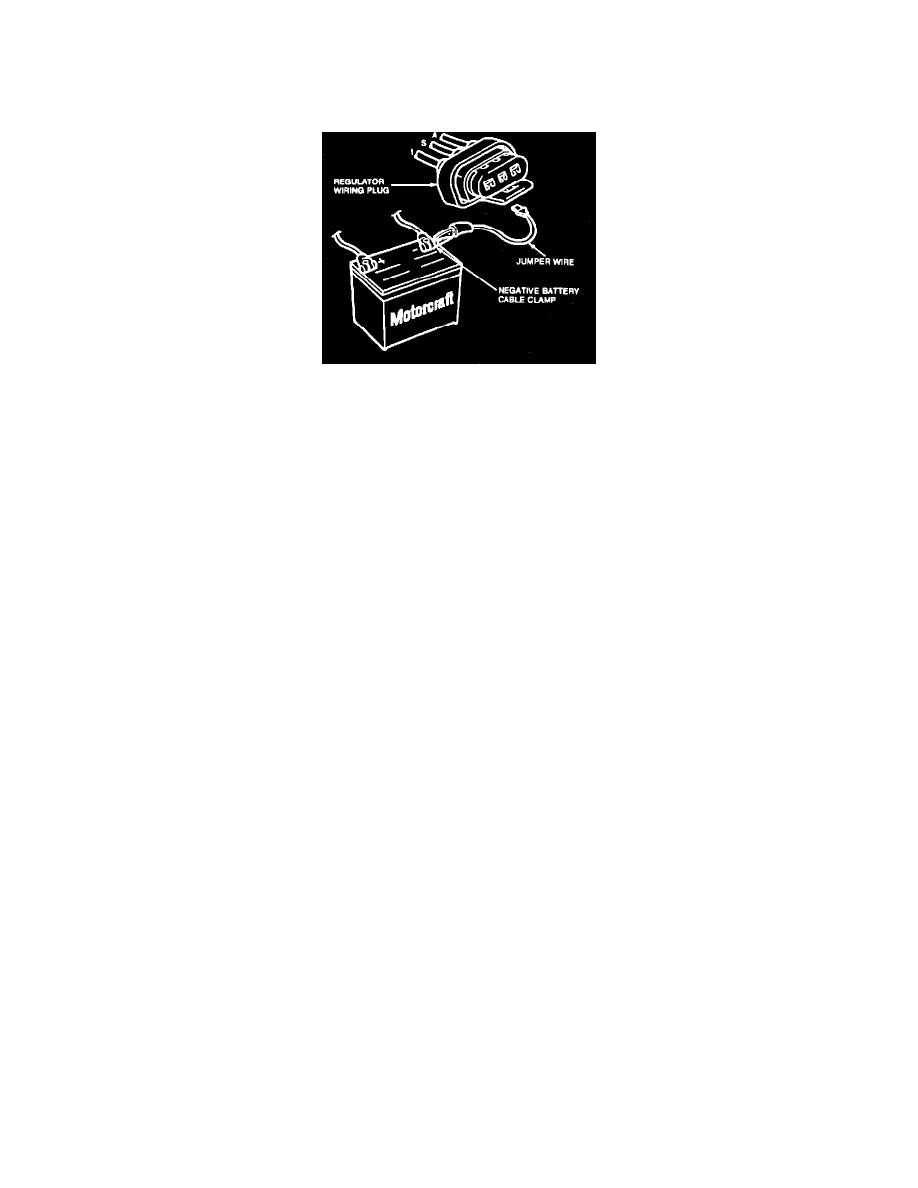
Fig. 5 Indicator Lamp Test. Integral Alternator Regulator (IAR)
The Integral Alternator Regulator (IAR) has a circuit in the regulator that will indicate a high battery voltage condition. With the IAR system, three
conditions can cause the charge indicator to come on during vehicle operation: no alternator output, over-voltage condition or under-voltage condition.
1.
If charge indicator does not come on, disconnect wiring connector from regulator Fig. 5 and connect a jumper wire from wiring connector I to
battery post cable clamp.
2.
Turn ignition to run position with engine off. If indicator lamp does not light, check for presence of bulb socket resistor. If resistor is missing,
replace bulb socket. If resistor is present, check for contact of bulb contact leads to the flexible printed circuit. If satisfactory, check indicator bulb
for continuity and replace bulb if burned out. If bulb is satisfactory, perform regulator I circuit test.
3.
If indicator lamp does light, remove jumper wire and reconnect electrical connector to regulator. Connect voltmeter negative lead to battery
negative post cable clamp and contact voltmeter positive lead to regulator A terminal screw. Battery voltage should be indicated. If battery voltage
is not indicated, service A wiring circuit.