
Taurus V6-195 3.2L DOHC SHO (1994)
Electronic Brake Control Module: Diagrams
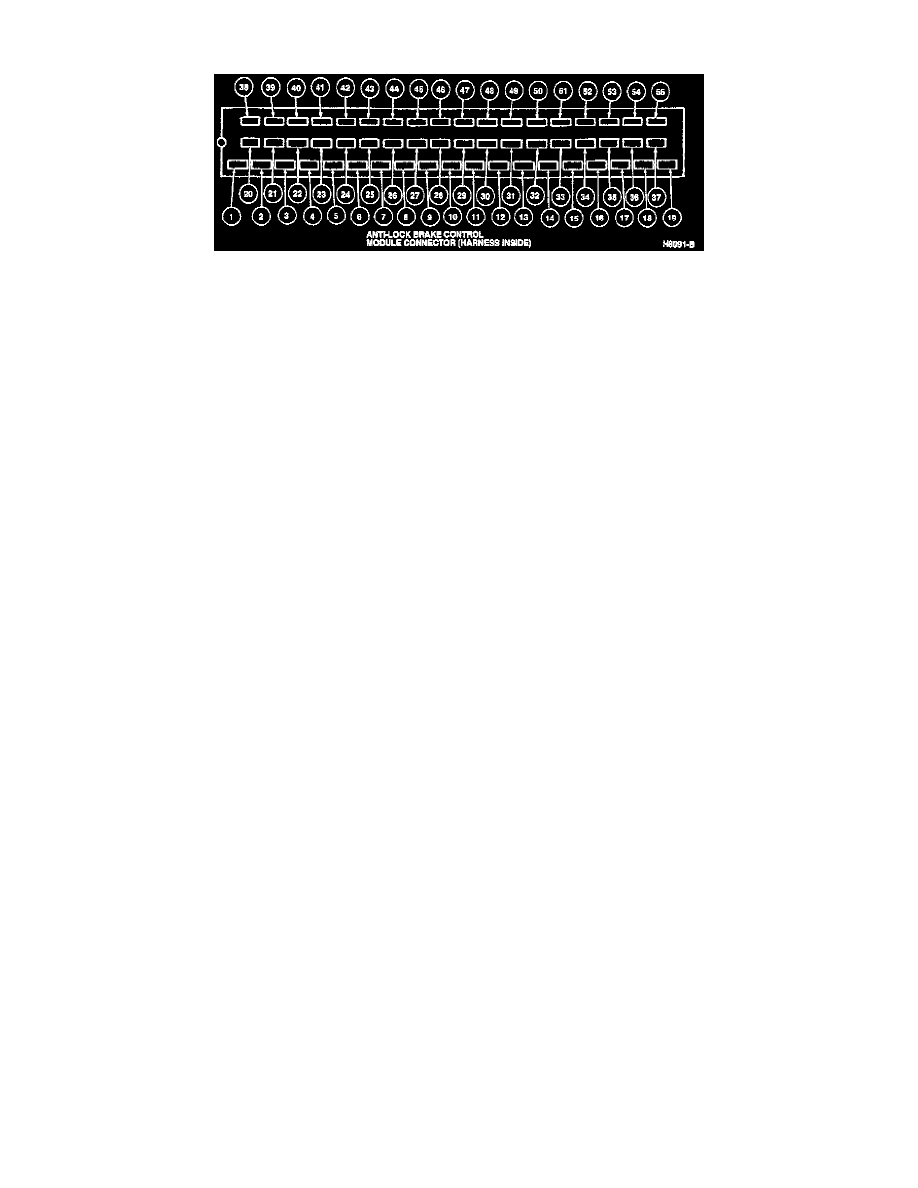
Connector
Pin Number
Circuit
Circuit Function
1
530 (LG/Y)
Ground
2
498 (PK)
ABS Valve Assembly
3
532 (O/Y)
ABS Power Relay
4
Not Used
5
549 (BR/W)
Anti-Lock Brake Pedal Sensor Switch
6
Not Used
7
Not Used
8
542 (Y)
Brake Fluid Level Switch No. 2
550 (Y/LG)(*)
9
Not Used
10
Not Used
11
Not Used
12
Not Used
13
Not Used
14
Not Used
15
539 (PK/LB)
Anti-Lock Motor Relay
16
Not Used
17
Not Used
18
599 (PK/LG)
ABS Valve Assembly
685 (BK/W)
(*)
19
530 (LG/Y)
Ground
20
495 (T)
ABS Valve Assembly
21
497 (W)
ABS Valve Assembly