
Taurus V6-195 3.2L DOHC SHO (1994)
Plastic O-Ring On Rack Piston Installation
4. Position plastic O-ring on Teflon(R) ring replacer T74P-3504-G, or equivalent, then slide tool and O-ring onto rack until they are adjacent to the
rack piston. Slide plastic O-ring off tool and into piston groove over rubber O-ring.
5. Apply lubricant ESB-M1C119-A, or equivalent, to rack teeth. Also apply a light coating of lubricant opposite rack teeth in yoke bearing contact
area.
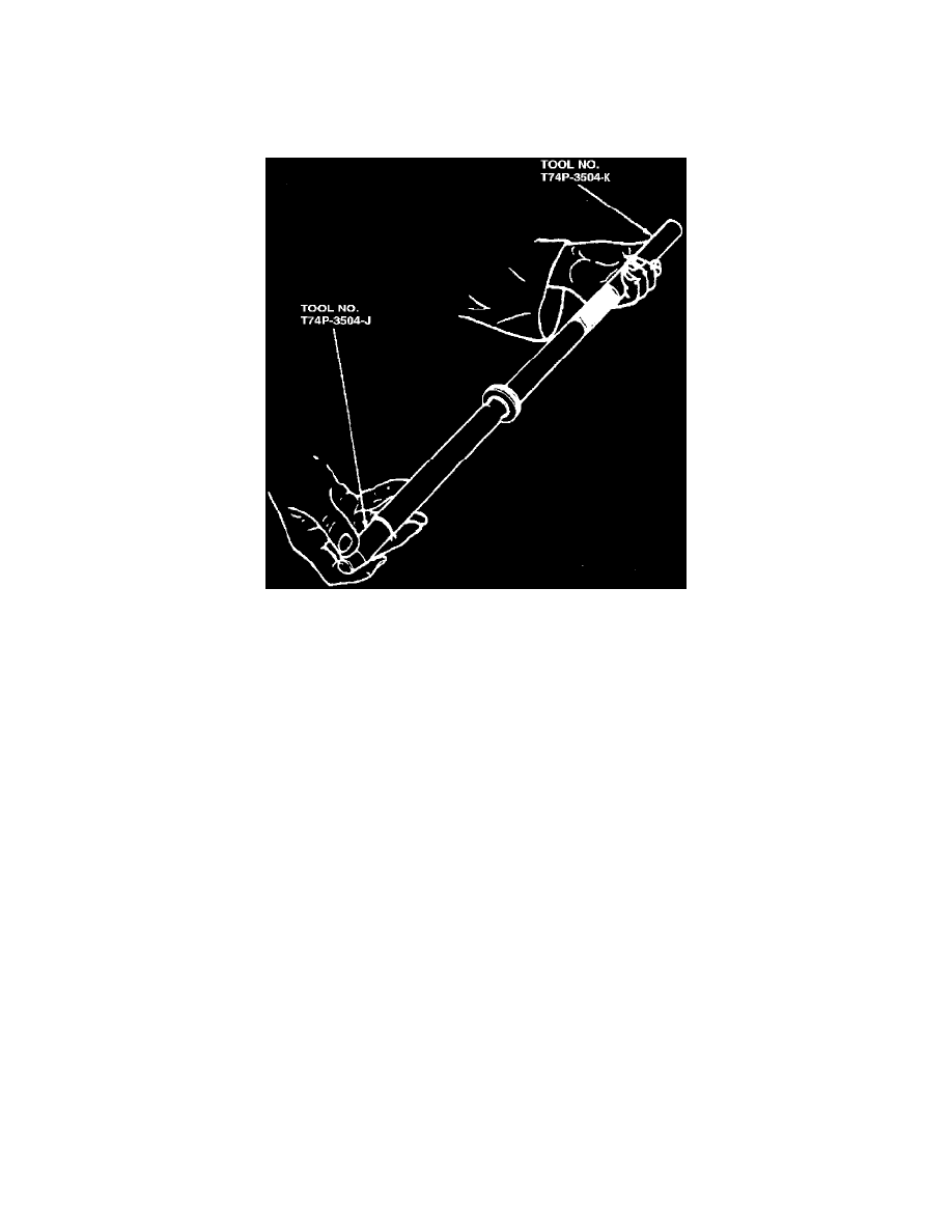
Positioning Sleeve Protector On Rack
6. Install protective sleeve T74P-3504-K, or equivalent, over rack gear teeth to prevent damage to integral oil seal in gear housing. Also thread rack
seal protector sleeve T74P-3504-J, or equivalent, over rack threads.
7. Lubricate plastic O-ring and protective sleeves with power steering fluid.
8. Position small diameter end of Teflon(R) ring sizing tool T78P-3504-M, or equivalent, into righthand side opening of gear housing.
9. Place rack toothed end first, into sizing tool, then carefully push rack into housing until leading end engages internal oil seal. Position sizing tool
so that it compresses plastic O-ring. Push rack into housing until protective sleeve protrudes from lefthand side of gear housing. Remove sizing
tool and long protective sleeve from end of rack. Install tie rod and ball socket assembly on left end of rack to prevent rack teeth from damaging
internal oil seal.
10. Install two O-rings on rack bushing.
11. Lubricate outer rack oil seal with gear lube, then using outer rack seal replacer T74P-3504-F, or equivalent, install oil seal in rack bushing with lip
spring facing inside of bushing.
12. Lubricate short protective sleeve on rack end and rack bushing O-rings with gear lube.
13. Start bushing with seal end first onto rack. Position bushing and seal over protective sleeve and into housing bore. Using Teflon(R) ring sizing tool
T78P-3504-M, or equivalent, apply hand pressure to end plate and rack bushing until bushing is seated in housing bore. If bushing will not seat
using hand pressure, tap bushing in using a 1 1/8 inch socket and a plastic mallet. Install snap ring and remove protective sleeve.
14. Install tie rod assemblies.
15. Install input shaft and valve assembly.
16. Fill yoke plug hole with 2 ounces of lubricant. Install yoke, spring, plug and locknut. Adjust yoke bearing preload.
17. If the external pressure lines were removed, they must be replaced with new pressure lines. Remove the copper seals from the pressure ports
previous to installation of new lines.
18. Apply lubricant under cuts in tie rod, then install bellows, equalizer tube, clamps, jam nuts and tie rod ends.
Input Shaft and Valve Assembly
DISASSEMBLY
1. Thoroughly clean steering gear housing, then mount gear in holding fixture T57L-500-B, or equivalent.
2. Do not remove the external pressure lines unless damaged or leaking. Loosen yoke plug locknut and yoke plug to relieve preload on rack.