
Taurus V6-195 3.2L DOHC SHO (1994)
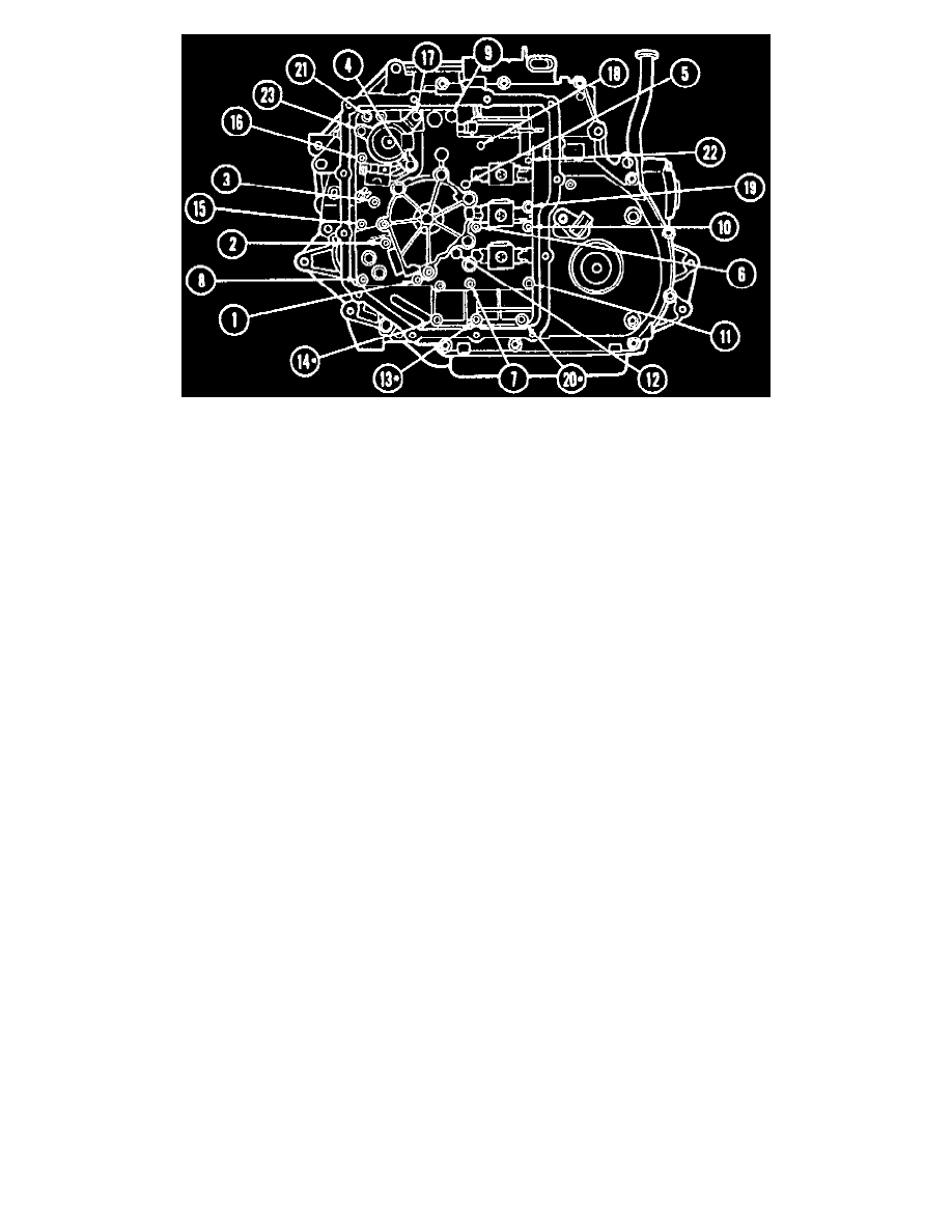
Oil Pump And Valve Body Bolt Tightening Sequence
6. On all models, use valve body guide pin tool No. T86P-70100-C or equivalent to position valve body, then install pump and valve body attaching
bolts, torque to 7-9 ft lbs, in sequence shown in the Oil Pump And Valve Body Bolt Tightening Sequence image.
NOTE: Do not use bolts to position pump and valve body assembly.
7. Install new gasket.
8. Connect upper bulkhead connector wiring to valve body.
9. Install side pan, then loosely install two upper pan attaching bolts.
10. Ensure proper pan gasket position, then install pan attaching bolts, torquing to 10-12 ft lbs.
11. Install lefthand engine mounts and supports, then install lefthand subframe attaching bolts.
12. Connect ride height sensor.
13. Install inner fender cover.
14. Install lefthand wheel and tire assembly.
15. Remove engine and transaxle support equipment, then lower vehicle.
16. Install radiator sight shield.
17. Remove engine lifting eyes.
18. Install brake reservoir hose.
19. Reposition supply hoses, vacuum lines, and wiring at valve body cover.
20. Install manual lever position sensor.
21. Install remote air cleaner.
22. Install battery tray and battery.
23. Fill transaxle with fluid to capacity.
24. Start engine, move transaxle selector lever through all ranges, checking pump and valve body cover for leakage.