
Taurus V6-232 3.8L (1989)
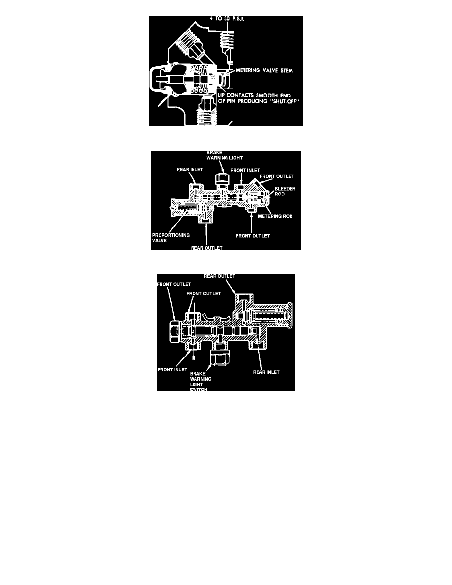
Fig. 11 Metering Valve, Continued Braking
Fig. 12 Three-way Combination Valve
Fig. 13 Two-way Combination Valve
Metering Valve
When the brakes are not applied, the metering valve permits the brake fluid to flow through the valve, thus allowing the fluid to expand and contract with
temperature changes.
When the brakes are initially applied, the metering valve stem moves to the left, preventing fluid to flow through the valve to the front disc brakes. This
is accomplished by the smooth end of the metering valve stem contacting the metering valve seal lip at 4-30 psi, Fig. 10. The metering valve spring holds
the retainer against the seal until a predetermined pressure is produced at the valve inlet port which overcomes the spring pressure and permits hydraulic
pressure to actuate the front disc brakes, Fig. 11. The increased pressure into the valve is metered through the valve seal, to the front disc brakes,
producing an increased force on the diaphragm. The diaphragm then pulls the pin, in turn pulling the retainer and reduces the spring pressure on the
metering valve seal. Eventually, the pressure reaches a point at which the spring is pulled away by the diaphragm pin and retainer, leaving the metering
valve unrestricted, permitting full pressure to pass through the metering valve.
On some applications, two-way or three-way combination valves are used. The three-way combination valve consists of a metering valve, failure warning
switch and a proportioner mounted in an aluminum body, Fig. 12. The two-way combination valve, Fig. 13, consists of a failure warning switch and a
proportioner. On models equipped with metering valves, the metering valve release rod must be pushed in during brake bleeding operations on the front
wheels.
On Capri models, the proportioning valves are an integral part of the master cylinder.