
Taurus V6-232 3.8L (1989)
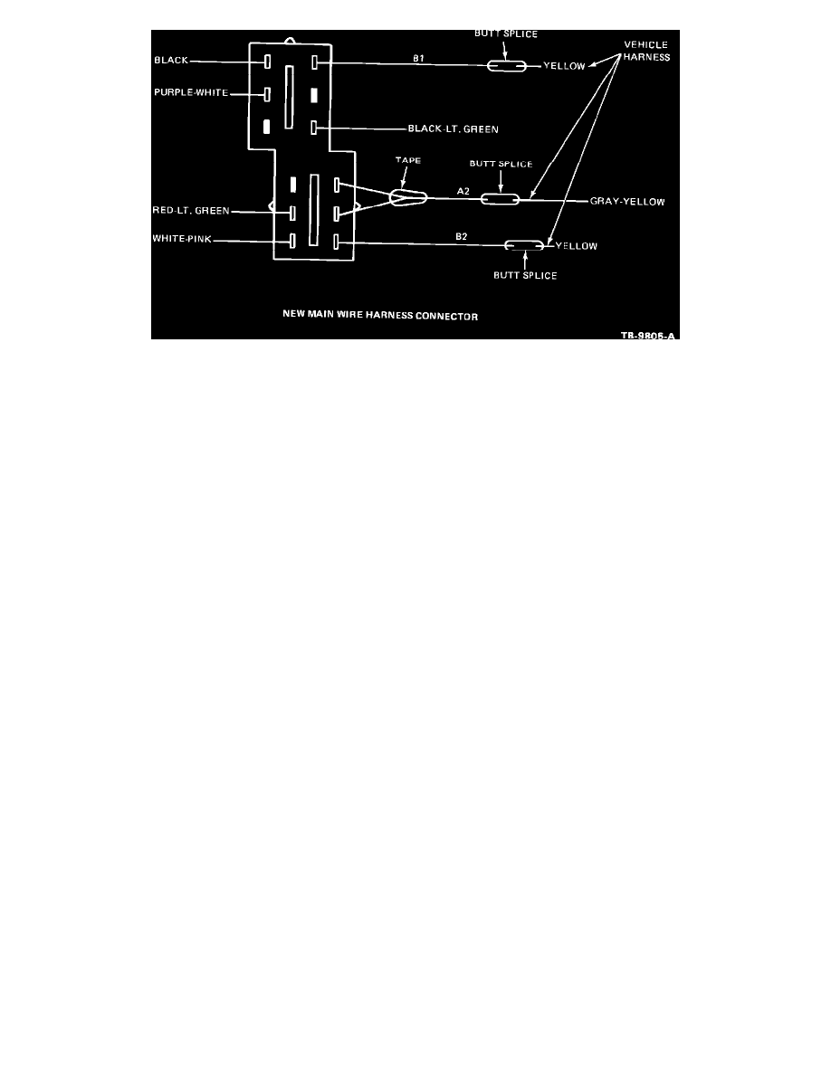
Figure 2
4. Cut the two (2) "YELLOW" wires six (6) inches (152 mm) from the ignition switch wire harness connector, Figure 2.
5. Cut the "YELLOW/GRAY" wire seven and a half (7.5) inches (191 mm) from the ignition switch wire harness connector, Figure 2.
6. Strip 1/8 of an inch (3 mm) of insulation from the ends of the three wires.
7. Using butt splice connectors, crimp the three ignition switch wires to the new service connector and wire harness assembly as follows:
a.
"YELLOW" ignition wire to "B1" service harness
b.
"YELLOW/GRAY" ignition wire to "A2" service harness
c.
"YELLOW" ignition wire to "B2" service harness
Refer to TSB 86-3-11 for butt splice instructions.
8. Install the five (5) remaining ignition switch wire terminals into the new ignition switch connector as shown in Figure 2.
9. Install the new ignition switch connector wedges and tape the area of repair with electrical tape.
10. Install the new ignition switch and plug in the new ignition switch connector.
NOTE:
REINSTALL AND ADJUST "PRNDL" CABLE AFTER THE STEERING COLUMN HAS BEEN REPOSITIONED.
11. Reconnect the negative battery cable.
PART NUMBER
PART NAME
CLASS
E8OY-11572-A
Ignition Wire Harness
BG
Modification Kit
OTHER APPLICABLE ARTICLES: 86-3-11
SUPERSEDES: 88-26-2
WARRANTY STATUS: Eligible Under Basic Warranty Coverage
OPERATION DESCRIPTION
TIME
900405A
Install Ignition Wire
1.4 Hrs.
Modification Kit
DEALER CODING
BASIC PART NO.
CONDITION CODE