
Taurus V6-232 3.8L (1989)
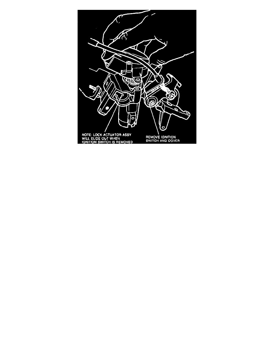
Fig. 6 Ignition Switch Removal
1.
Remove ignition lock as described in IGNITION LOCK.
2.
On models with tilt columns, remove tilt release lever attaching screw then the lever.
3.
On all models, remove lower instrument panel attaching screws, then the panel.
4.
Remove steering column shroud attaching screws, then the shroud.
5.
Remove steering column to support bracket attaching nuts and bolts, then lower steering column.
6.
Disconnect ignition switch electrical connector, Fig. 4.
7.
Remove lock actuator cover plate attaching bolt, Fig. 5, then the cover plate. The lock actuator assembly is free to slide out of cylinder
housing.
8.
Remove ignition switch attaching screws, then the ignition switch, Fig. 6.
9.
Ensure replacement ignition switch is in the Run position by fully rotating driveshaft clockwise to Start position and releasing.
10.
Install lock actuator assembly to a depth of .46-.54 inch from the bottom of actuator assembly to bottom of lock cylinder housing.
11.
While holding actuator at proper depth, install ignition switch and cover. Attach with two tamper-resistant Torx head screws. Torque screws to
30-48 inch lbs.
12.
Install lock cylinder, then rotate ignition switch to the Lock position. Measure depth of actuator assembly as outlined in step 10 above. Actuator
assembly must be .92-1.00 inch inside lock cylinder housing. If measurement is not within specifications, actuator assembly must be removed and
reinstalled.
13.
Install lock actuator cover plate with tamper-resistant Torx head screw. Torque screw to 30-48 inch lbs.
14.
Install ignition switch electrical connector, then connect battery ground cable.
15.
Ensure ignition switch works properly at all functions and the steering column locks functions properly.
16.
Remove ignition lock cylinder as outlined elsewhere in this section.
17.
Align steering column mounting bracket with steering column bracket and install mounting bolts and nuts. Torque to 15-25 ft. lbs.
18.
Install steering column shrouds, then instrument panel lower cover.
19.
On models with tilt columns, install tilt lever and tilt lever mounting screw. Torque screw to 6.5-8.5 inch lbs.
20.
On all models, install ignition lock cylinder.