
Taurus V6-232 3.8L (1989)
c. Remove right side halfshaft and linkshaft from vehicle as an assembly.
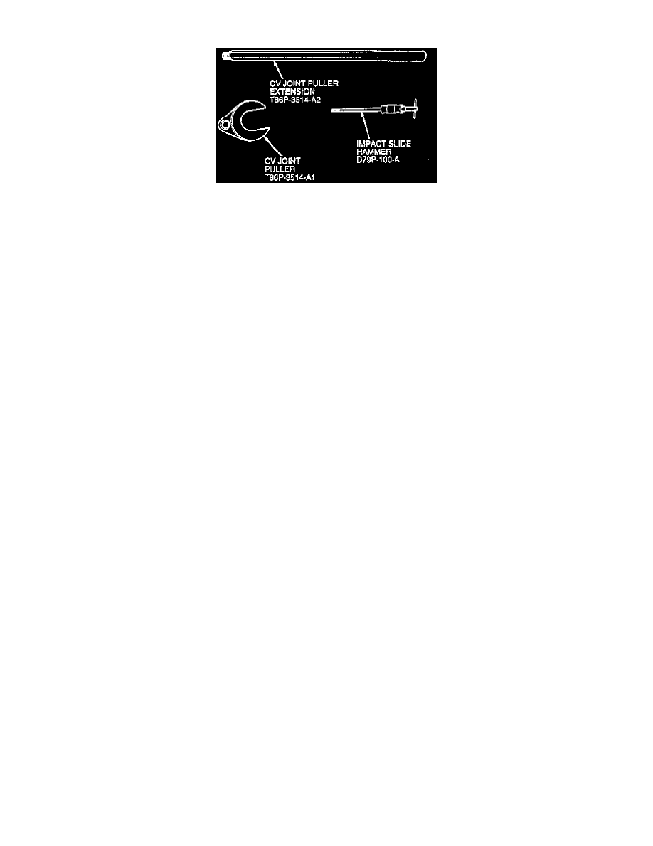
Fig. 2 Inboard CV joint removal tools. Except models equipped w/AXOD
7.
To remove both halfshafts on models equipped with Automatic Overdrive Transaxle (AXOD) or left side halfshaft on models equipped with
manual transaxle, proceed as follows:
a. Turn steering hub to one side or wire and/or wire strut assembly aside.
b. Using puller tools shown in Fig. 2, attached to the inboard side of the inboard CV joint, remove CV joint from transaxle.
c. Support end of shaft in horizontal position with suitable wire. Do not allow shaft to hang unsupported as damage to the outboard CV
joint can result.
d. Separate hub assembly from outer CV joint using hub remover T81P-1104-C, adapters T83P-1104-BH, T86P-1104-A1 and T81P-1104-A or
equivalent, Fig. 3. Never use a hammer to separate hub assembly from outer CV joint as damage to the CV joint threads and internal
components may result.
e. Remove halfshaft from vehicle.
8.
To remove left side halfshaft from models equipped with Fluid Lockup Converter (FLC), proceed as follows. If removing both right and left
side halfshafts, plugs T81P-1177-B or equivalent must be installed. Failure to do so may result in dislocation of differential side gears,
necessitating transaxle disassembly to re-align the gears.
a. Remove right side halfshaft assembly from the transaxle case and secure it in a horizontal position to the underside of vehicle, then remove left
side halfshaft by inserting driver T81P-4026-A or equivalent into right side halfshaft opening and driving left side halfshaft and CV joint from
transaxle.
b. Support end of shaft in horizontal position with suitable wire. Do not allow shaft to hang unsupported as damage to the outboard CV
joint can result.
c. Separate hub assembly from outer CV joint using hub remover T81P-1104-C, adapters T83P-1104-BH, T86P-1104-A1 and T81P-1104-A or
equivalent, Fig. 3. Never use a hammer to separate hub assembly from outer CV joint as damage to the CV joint threads and internal
components may result.
d. Remove halfshaft from vehicle.
9.
Prior to installation install new circlip on inboard CV joint stub shaft and/or linkshaft. The original circlip cannot be reused. On models
equipped with manual transaxle and FLC, torque linkshaft bearing to 16-23 ft. lbs.
10.
Align CV joint splines with transaxle differential splines, then push CV joint into differential splines until circlip is felt to seat inside side gears.
Some force may be necessary to insert CV joints. Ensure differential oil seal is not damaged during installation. If difficulty is
encountered installing CV joints, a non-metallic mallet may be used on the outside joint CV joint stub shaft.
11.
Align CV joint splines with hub splines, then install stub shaft in hub as far as possible.
12.
Temporarily fasten rotor to hub with two lug nuts and suitable washers. Install steel rod between lug nuts and use to prevent rotor from turning.
13.
Install hub washer and new hub nut, then manually thread nut onto CV joint stub shaft as far as possible.
14.
Connect steering knuckle to lower ball joint stud, then install new nut and bolt and torque to 40-55 ft. lbs.
15.
On models equipped with anti-lock brakes, install ABS sensor.
16.
On all models, connect stabilizer bar to stabilizer bar link, torque to 38-48 ft. lbs.
17.
Install wheel and tire assembly, then lower vehicle to ground. Torque hub nut to 180-200 ft. lbs., torque wheel lug nuts to 80-105 ft. lbs.
18.
Top off transaxle with lubricant using ESP-M2C185-A Mercon or equivalent.