
Taurus V6-3.0L DOHC VIN S (2000)
8. Carefully pry up between the air bag module backing plate and the steering wheel and remove the driver air bag module.
NOTE: Position any wire harnesses or electrical connectors out of the way prior to removing the driver air bag module.
INSTALLATION
1. WARNING: When installing a driver air bag module (soft pack), make sure there are no foreign objects in the steering wheel cavity or in
the driver air bag module (soft pack). Failure to do so may result in personal injury in the event of an air bag deployment.
WARNING: Do not dislodge the fabric from the air bag module (soft pack). In the event that the air bag fabric becomes dislodged, install a
new air bag module (soft pack). Failure to do so may result in personal injury in the event of an air bag deployment.
WARNING: Be careful not to pinch the air bag fabric between the steering wheel and the air bag module housing. In the event the fabric
becomes pinched install a new air bag module (soft pack). Failure to do so may result in the air bag not functioning correctly.
WARNING: Make sure the horn wiring is routed out between the air bag (soft pack) backing plate and the steering wheel. Failure to do so
may result in the air bag (soft pack) not functioning correctly.
Position the air bag module into the steering wheel.
1. While positioning the air bag module into the steering wheel, position the horn wire harness (black sheathing with red connector) through the
opening in the air bag module backing plate, so that any extra horn wire harness is not in the steering wheel cavity, pinched between the air bag
module and steering wheel.
2. Position the air bag module so that the steering wheel positioning sleeves go through the air bag module backing plate alignment holes and the
air bag module backing plate lies flat on the steering wheel all the way around.
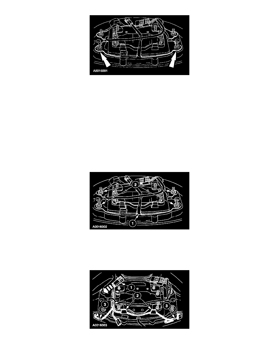
2. Install the component feed electrical connector and wire harness onto the wire shield.
1
Slide the component feed electrical connector onto the wire shield.
2
Route the component feed wire harness between the wire shield retaining clips.