
Taurus V6-3.0L DOHC VIN S (2000)
^
If two or more weld nuts are missing, do not install the "J" nuts as outlined in this procedure. Weld Nut Repair-Missing Weld Nut, Restraints
Control Module (RCM) and Side Crash Sensor Weld nuts must be installed as outlined in Weld Nut Repair - Missing Weld Nut, Restraints
Control Module (RCM) and Side Crash Sensor.
^
The following procedure applies to vehicles that have a rectangular hole in the sheet metal that is in close proximity to the missing weld nut.
1. Obtain a "J" nut (part number N623332-5301) or any of the following optional "J" nuts (part numbers: N623342-S101, N800854-S100,
N800925-S 100).
2. Obtain a 6 mm (0.24 in) grounding screw (part number N8063 27-S190) or equivalent.
3. Install the "J" nut through the rectangular hole in the sheet metal.
4. Install the crash sensor.
NOTE: Be sure the threaded portion of the "J" nut is aligned with the clearance hole in the sheet metal.
5. Tighten the attaching screws to specification.
Missing Weld Nut-Restraints Control Module & Side Crash Sensor
WARNING: TO AVOID ACCIDENTAL DEPLOYMENT AND POSSIBLE PERSONAL INJURY, THE BACKUP POWER SUPPLY MUST
BE DEPLETED BEFORE REPAIRING OR REPLACING ANY FRONT OR SIDE AIR BAG SUPPLEMENTAL RESTRAINT SYSTEM
(SRS) COMPONENTS AND BEFORE SERVICING, REPLACING, ADJUSTING OR STRIKING COMPONENTS NEAR THE FRONT OR
SIDE AIR BAG SENSORS, SUCH AS DOORS, INSTRUMENT PANEL, CONSOLE, DOOR LATCHES, STRIKERS, SEATS AND HOOD
LATCHES.
DETERMINE LOCATION OF THE FRONT AIR BAG SENSORS.
THE SIDE AIR BAG SENSORS ARE LOCATED AT OR NEAR THE BASE OF THE B-PILLAR.
TO DEPLETE THE BACKUP POWER SUPPLY ENERGY, DISCONNECT THE BATTERY GROUND CABLE AND WAIT AT LEAST
ONE MINUTE. BE SURE TO DISCONNECT AUXILIARY BATTERIES AND POWER SUPPLIES (IF EQUIPPED).
NOTE:
^
There are two procedures to repair a vehicle having missing air bag crash sensor attaching weld nut(s). Read both this procedure and Weld Nut
Repair - "J" Nut, Restraints Control Module (RCM) and Side Crash Sensor before proceeding with the repair.
^
Use only this procedure if two or more weld nuts are missing, do not install the "J" nuts as outlined in Weld Nut Repair - "J" Nut, Restraints
Control Module (RCM) and Side Crash Sensor.
^
Radiator support repair shown, others are similar.
1. Obtain a 6 mm (0.24 in) weld nut.
2. Obtain a 6 mm (0.24 in) grounding screw.
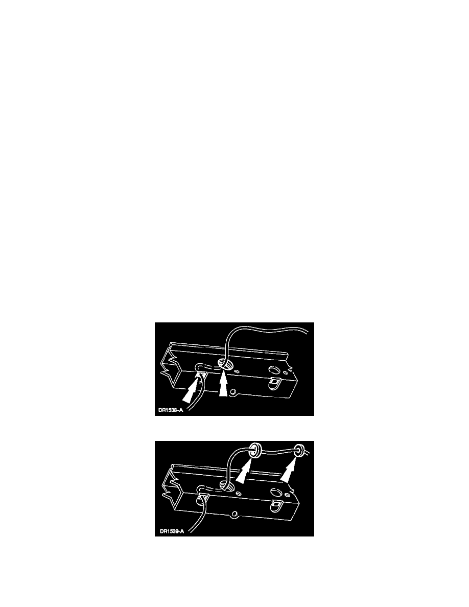
3. Route a sufficient length of copper welding wire through the weld nut clearance hole and back out an adjacent access hole.
4. Feed the copper welding wire through the weld nut, then through a standard flat washer.
5. Secure the flat washer so that it cannot be pulled off the end of the copper welding wire.
6. Pull the copper welding wire back through the clearance hole, allowing the weld nut and flat washer to follow the copper welding wire through.
7. Position the weld nut to the weld nut clearance hole, firmly pulling on the copper welding wire allowing the secured flat washer to hold the weld