
Taurus V6-3.0L VIN 2 Flex Fuel (1997)
Brake Rotor/Disc: Testing and Inspection
Runout
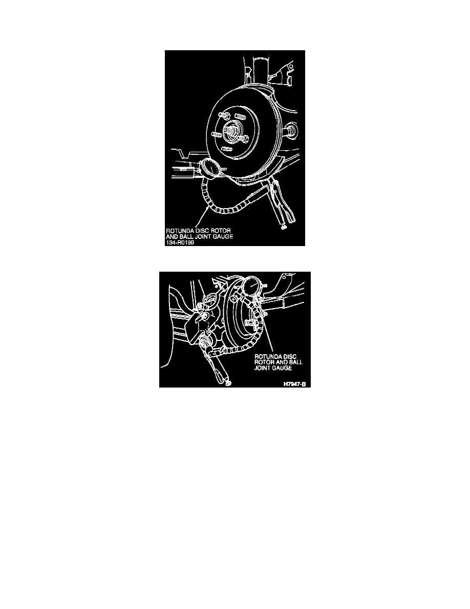
Rotor Runout Setup, Front
Rear Rotor Runout
NOTE: Brake pulsation/brake roughness that is present during brake application is caused by either foreign material build-up or contamination on the
rotor brake surface or uneven brake rotor thickness caused by runout.
1. Remove brake caliper and anchor plate.
NOTE: Make sure all mating surfaces between the hub flange and the rotor are clean and free of rust or contaminants to prevent an erroneous reading.
2. Mount the rotor with all wheel nuts firmly tightened.
3. Make sure the axle wheel hub retainers are tight and the wheel bearings are not worn to eliminate all end play from the wheel hubs.
4. Mark a stud-to-rotor beginning index point.
5. Attach Rotunda Disc Rotor and Ball Joint Gauge 134-R0199 or equivalent to some part of the vehicle suspension so the stylus of the indicator
touches the surface of the disc brake rotor approximately 25.4 mm (1 inch) from outer edge of the disc brake rotor.
6. Adjust the dial indicator to mid travel. Zero the scale on the dial indicator. Slowly turn the disc brake rotor one complete turn and note the high and
low readings on the dial. The difference between the high and low readings must not exceed the runout specification.
-
Front Max Allowable Runout On Vehicle, 0.08mm (0.003 inch)
-
Rear Max Allowable Runout On Vehicle, 0.10mm (0.0004 inches)
NOTE: The gauge can remain mounted at the same location. Loosen the tension on the flexible gauge arm and move the dial indicator well away from
the area and tighten while components are being removed or installed.