
Taurus V6-3.0L VIN 2 Flex Fuel (1997)
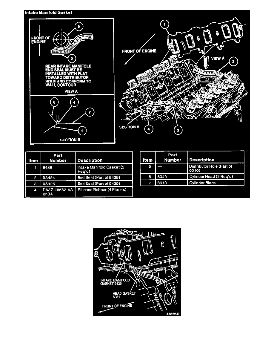
Fig. 10 Lower Intake Manifold
4. Apply a 5-6 mm (1/4-inch) drop of Silicone Rubber D6AZ-19562-AA or BA or equivalent meeting Ford specifications ESB-M4G92-A and
ESE-M4G195-A to intersection of cylinder block (7) and cylinder head (6) at four corners (4).
5. Position intake manifold gasket onto cylinder heads. Align intake manifold gasket locking tabs to provisions on head gaskets.
6. Install front and rear intake manifold end seals. Secure with retainers.
7. Carefully position lower intake manifold, aligning intake manifold bolt holes to those in cylinder head. Use care to prevent disturbing silicone
sealer which can cause sealing voids.