
Taurus V6-3.0L VIN 2 Flex Fuel (1997)
b. downshift
c. coasting
d. engagement
4. If concern involves noise or vibration, does it relate to any of the following:
a. rpm
b. vehicle speed
c. shift
d. gear
e. range
f.
temperature
5. Vehicle must be at normal operating temperature.
6. Check transmission fluid level and condition.
7. Check for the following items:
a. vehicle modifications
b. electronic add-on items
c. leaks
d. proper linkage adjustments
8. Check TSB's for related information.
9. Perform complete On-Board Diagnostics (OBD) for both KOEO and KOER.
10. Record all DTCs.
11. Repair all non-transaxle DTCs.
INSTALLATION PROCEDURES
NOTE:
^
Installing the Transmission Tester at the TR sensor CONNECTOR allows the separation of the vehicle electronics from the TR sensor
electronics.
^
During tester usage additional DTCs may be set. Therefore, it is important that all codes are erased after service has been made. To verify
elimination of all DTCs, rerun On-Board Diagnostic.
^
The electrical and vacuum diagrams should be referenced to assist in diagnosis of electronically-controlled transmissions:
1. Disconnect vehicle harness at transaxle TR sensor.
2. Set the two-way switch in the down position. (This switch will stay in the same position for all TR sensor testing.)
3. Attach the TR/MLP Sensor overlay to the Transmission Tester.
NOTE: Affixing the overlay will immobilize the two-way switch (set in Step 2) so it cannot be accidentally moved to an incorrect setting during
testing.
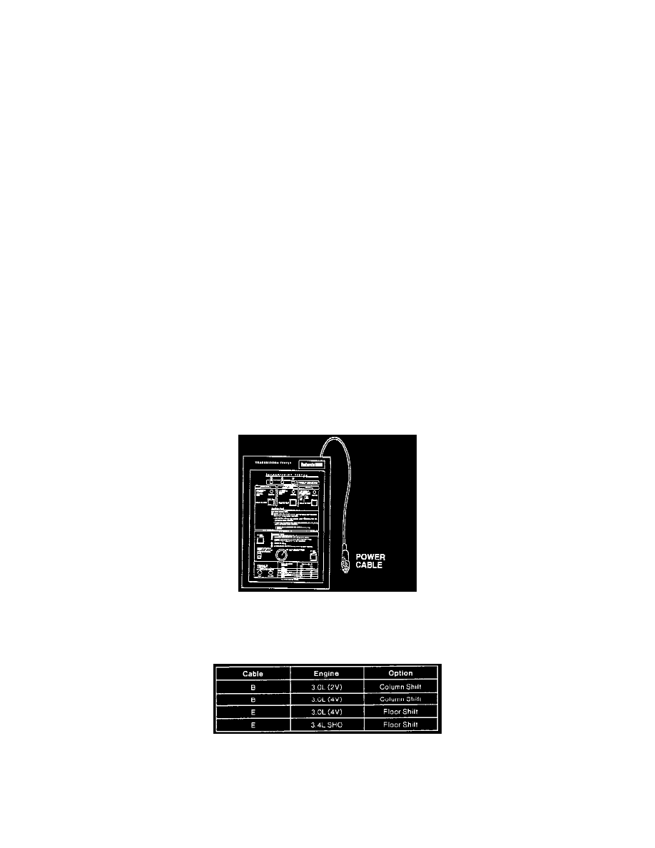
Interface Cable Applications