
Taurus V6-3.0L VIN 2 Flex Fuel (1997)
Removing Forward Clutch Support Snap Ring
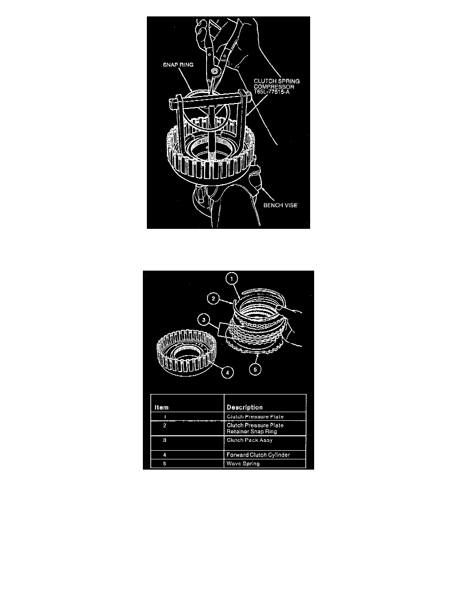
2. Install forward clutch support and spring and snap ring using Clutch Spring Compressor T65L-77515-A.
3. Install clutch wave spring, clutch pack, clutch pressure plate and clutch pressure plate retainer snap ring.
4. Check clutch pack clearance using feeler gauge or Dial Indicator with Bracketry TOOL-4201-C or equivalent. Push downward on the clutch pack
firmly. Release pressure and zero dial indicator. Lift clutch pressure plate to the bottom of the snap ring. Note dial indicator reading. Take two
readings, 180° apart, and determine the average of the two readings. The clearance should be 1.52-1.90 mm (0.060-0.075 inch). If the clearance is
not within specification, selective snap rings are available in the following thickness:
Thickness: Part Number
1.24-1.34 mm (0.049-0.053 inch): E6SP-7G367-AA
1.60-1.70 mm (0.063-0.067 inch): E6SP-7G367-BA
1.95-2.05 mm (0.077-0.081 inch): E6SP-7G367-CA
2.30-2.40 mm (0.091-0.094 inch): E6SP-7G367-DA
2.65-2.75 mm (0.104-0.108 inch): E6SP-7G367-EA