
Taurus V6-3.0L VIN 2 Flex Fuel (1997)
4. Install Valve Body Guide Pin T86P-70100-A. install two Torx bolts in main control valve body and tighten to 9-12 Nm (80-106 inch lbs.).
Remove alignment pins.
Installation
1. Install a new pump and main control valve body-to-chain cover gasket onto chain cover.
2. Carefully slide pump assembly and main control valve body over pump shaft and onto chain cover.
3. For vehicles without ABS:
a. Remove manual shift valve from main control valve body.
b. Rotate the main control valve body as necessary to allow engagement between the pump shaft and pump assembly. If complete engagement
has been obtained, the main control valve body should slide flush onto chain cover with little effort.
c. After full engagement between the pump shaft and pump assembly has been obtained, align main control valve body to installation position
and install manual shift valve.
NOTE: On vehicles equipped with anti-lock brake system (ABS), the hydraulic modulator may not afford enough clearance to sufficiently rotate
the pump assembly and main control valve body to complete engagement between the pump shaft and pump assembly. It may be necessary to
rotate the crankshaft using a 7/8-inch deep well socket on the crankshaft pulley to complete the engagement of the pump shaft with the pump
assembly.
4. Rotate pump assembly and main control valve body clockwise and connect manual valve link with manual shift valve.
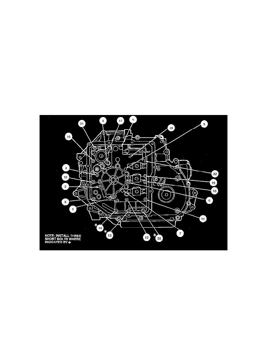
Pump Assembly And Main Control Valve Body Bolt Installation Sequence
5. Use Valve Body Guide Pin T86P-70100-C to position main control valve body and install pump assembly and main control valve body retaining
bolts. Tighten bolts to 9-12 Nm (80-106 inch lbs) in sequence shown in the Pump Assembly And Main Control Valve Body Bolt Installation
Sequence image.
CAUTION: Do not use pump assembly and main control valve body bolts to draw pump and main control valve body onto chain cover.
Component damage may result.
6. Install transaxle wiring harness into chain cover.
7. Connect transmission fluid temperature sensor and solenoid electrical connectors to solenoids and main control valve body.
8. Install main control cover with new gasket to chain cover. Secure transaxle side pan with transaxle side pan bolts and tighten to 10-12 Nm (89-106
inch lbs.).
9. Install LH engine support and insulator.
10. Install LH front fender splash shield.
11. Install LH front wheel tire and wheel assembly.