
Taurus FWD V6-3.5L (2008)
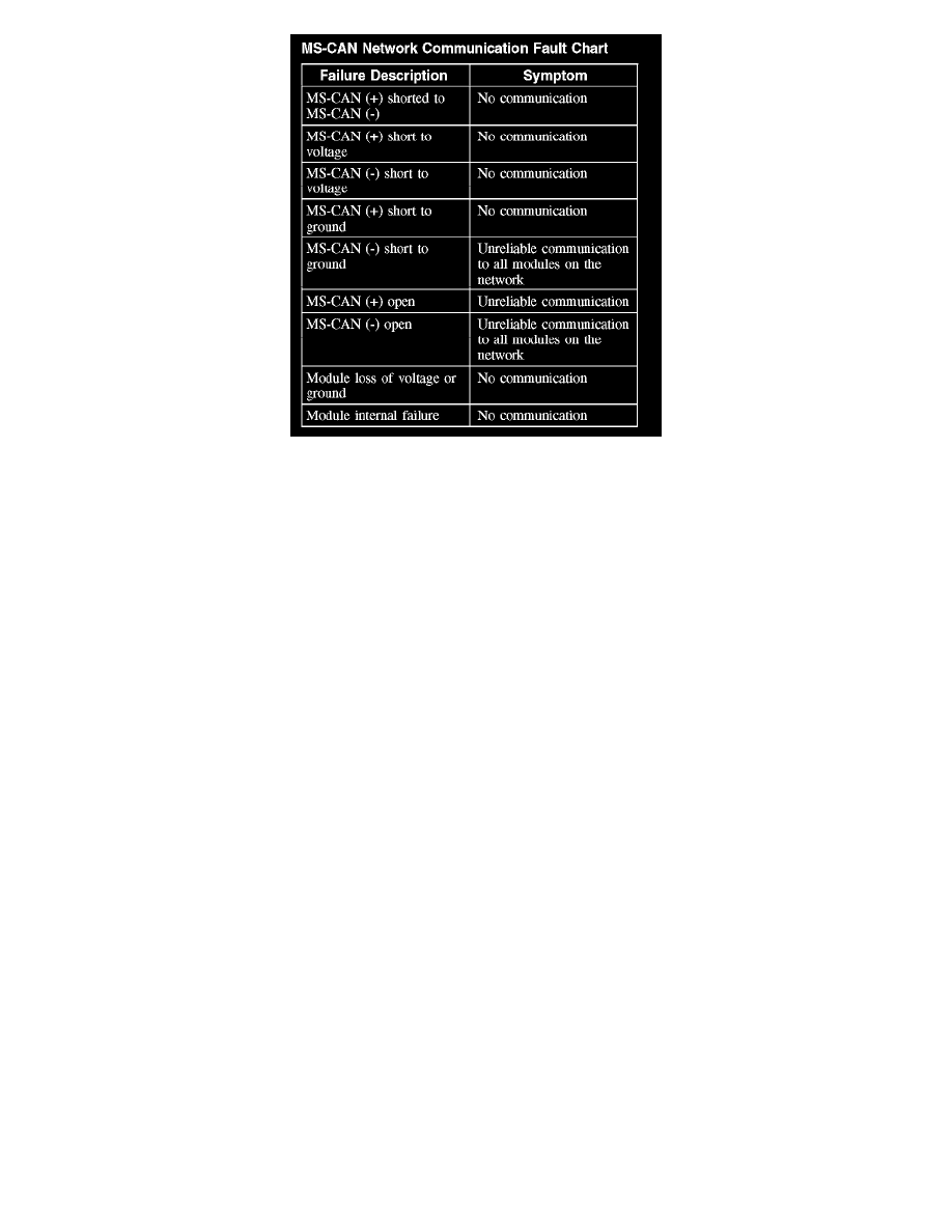
MS-CAN Network Communication Fault Chart
HS-CAN
The HS-CAN network uses an unshielded twisted pair cable of data (+) and data (-) circuits. The data (+) and the data (-) circuits are each regulated to
approximately 2.5 volts during neutral or rested network traffic. As bus messages are sent on the data (+) circuit, voltage is increased by
approximately 1.0 volt. Inversely, the data (-) circuit is reduced by approximately 1.0 volt when a bus message is sent. Multiple bus messages can be
sent over the network CAN circuits allowing multiple modules to communicate with each other. The HS-CAN is a high speed communication network
used for the instrument cluster, the PCM, the Power steering control module, the four wheel drive (4WD) control module, the restraints control
module (RCM) the occupant classification sensor (OCS) module, and the ABS module communications, and designed for real time information
transfer and control. The HS-CAN network will not communicate while certain faults are present, but will operate with diminished performance with
other faults present. The HS-CAN bus may remain operational when 1 of the 2 termination resistors are not present.
In the event that one of the 2 network circuits (HS-CAN + or HS-CAN -) becomes open to a module on the network, unreliable network
communication to all modules on the network may result. The module to which the network circuit is open may repeatedly send network messages
indicating there has been partial data received. This type of message is referred to as a negative-acknowledge (NACK) message. Repeated NACK
messages may "load" the network with too much activity causing intermittent no communication to other network modules and/or the scan tool.
The following fault chart describes the specific HS-CAN network failures and their resulting symptom: