
Taurus FWD V6-3.5L (2008)
Part 2
Removal
WARNING:
-
Always carry or place a live air bag module with the air bag and deployment door/trim cover/tear seam pointed away from the body.
Do not set a live air bag module down with the deployment door/trim cover/tear seam face down. Failure to follow these instructions
may result in serious personal injury in the event of an accidental deployment.
-
Never probe the electrical connectors on air bag, safety canopy or side air curtain modules. Failure to follow this instruction may
result in the accidental deployment of these modules, which increases the risk of serious personal injury or death.
-
Do not repaint air bag modules with discolored or damaged trim covers or deployment doors; new air bag modules must be installed.
Failure to follow this instruction may result in the air bag deploying incorrectly, which increases the risk of serious personal injury or
death in a crash.
-
To reduce the risk of accidental deployment, do not use any memory saver devices. Failure to follow this instruction may result in
serious personal injury or death.
NOTE:
-
The air bag warning indicator illuminates when the restraints control module (RCM) fuse is removed and the ignition switch is ON. This is
normal operation and does not indicate a supplemental restraint system (SRS) system fault.
-
The SRS must be fully operational and free of faults before releasing the vehicle to the customer.
-
Repair is made by installing a new part only. If the new part does not correct the condition, install the original part and carry out the diagnostic
procedure again.
-
Follow each step of the procedure precisely to make sure of correct driver air bag module removal and installation.
-
Taurus/Sable shown, Taurus X similar.
1. Depower the SRS.
CAUTION: Do not service the driver air bag module using prior model year driver air bag module service procedures. Failure to follow
this instruction may result in component damage.
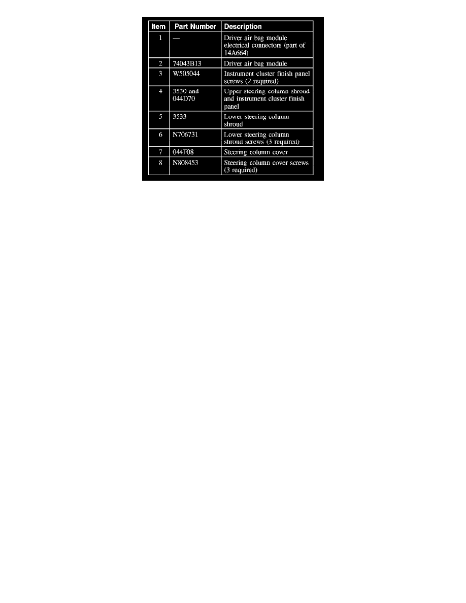
2. Remove the 3 screws and steering column cover.
3. Remove the lower steering column shroud.
-
Remove the 3 screws.
-
Unclip the lower steering column shroud from the upper steering column shroud and remove the shroud.
4. Remove the 2 screws from the instrument cluster finish panel.
5. Pry the instrument cluster finish panel forward.
-
If equipped, disconnect the in-vehicle temperature sensor assembly from the instrument cluster finish panel