
Taurus FWD V6-3.5L (2008)
3. NOTE: The hex holding feature can be used to prevent turning of the stud while removing the nut.
Remove the 2 tie-rod end nuts and disconnect the tie-rod ends from the wheel knuckles.
^
To install, tighten to 115 Nm (85 lb-ft).
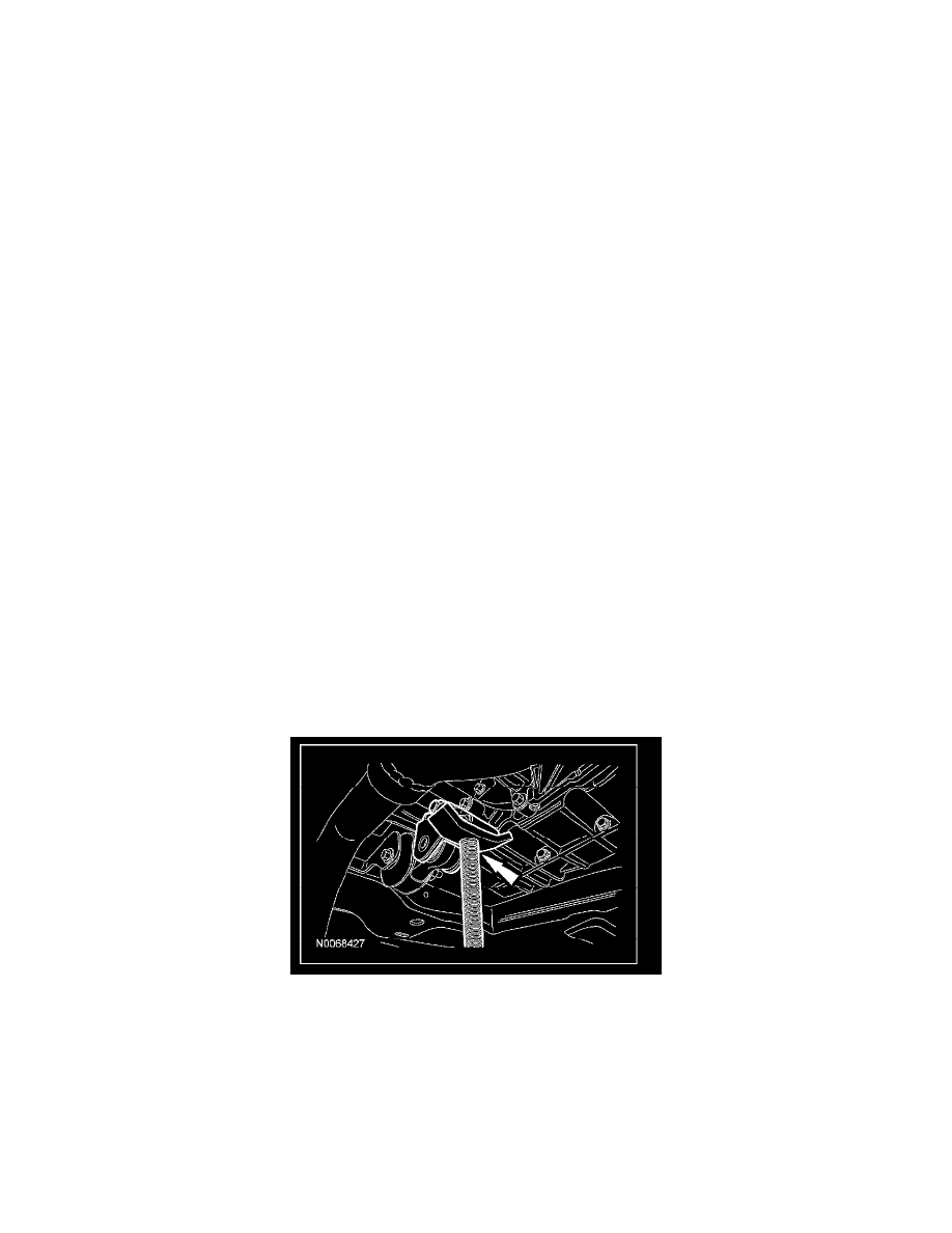
4. Remove the power steering pressure line bracket-to-steering gear bolt.
^
To install, tighten to 25 Nm (18 lb-ft).
5. CAUTION: Whenever the power steering lines are disconnected, new 0-ring seals must be installed. Make sure that the 0-ring seals are
installed in the correct order or a fluid leak may occur.
Remove the power steering line clamp plate bolt.
^
Rotate the clamp plate and disconnect the power steering pressure and return lines from the steering gear.
^
Discard the 2 0-ring seals.
^
To install, tighten to 25 Nm (18 lb-ft).
6. CAUTION: Do not allow the steering column shaft to rotate while the lower shaft is disconnected or damage to the clockspring may
result. If there is evidence that the shaft has rotated, the clockspring must be removed and recentered.
Remove the steering column shaft-to-steering gear bolt and disconnect the shaft from the steering gear.
^
Discard the bolt.
^
To install, tighten the new bolt to 25 Nm (18 lb-ft).
7. NOTE: The hex holding feature can be used to prevent turning of the stud while removing the nut.
Remove and discard the 2 stabilizer bar link upper nuts.
^
To install, tighten the 2 new nuts to 55 Nm (41 lb-ft).
^
Position the stabilizer bar and links upwards.
Taurus and Sable all wheel drive (AWD) vehicles
8. Remove the roll resistor bracket-to-transaxle nut and bolt.
^
To install, tighten to 48 Nm (35 lb-ft).
9. CAUTION: The jack must be placed under the roll resistor-to-transaxle engine bracket. Do not allow the jack to contact the engine or
transaxle or damage to the engine and/or transaxle may occur.
Place a suitable jack under the roll resistor-to-transaxle bracket.
^
Raise the engine/transaxle approximately 25.4 mm (1 inch).
All vehicles
10. Remove the 2 steering gear nuts and bolts.
^
Remove the steering gear from the left side of the vehicle.
^
Discard the nuts.
^
To install, tighten the 2 new nuts to 117 Nm (86 lb-ft).
11. NOTE: Whenever the power steering lines are disconnected, new 0-ring seals must be installed.
To install, reverse the removal procedure.
^
Fill the power steering system.