
Taurus X AWD V6-3.5L (2009)
3. Recover the refrigerant.
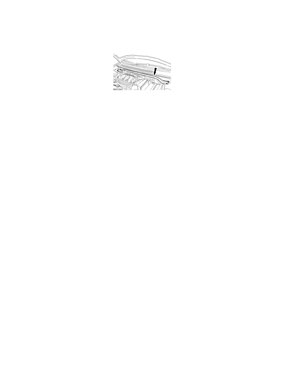
4. Remove the 4 cross vehicle beam nuts and remove the beam.
-
Detach the wire harness retainer.
-
To install, tighten to 30 Nm (22 lb-ft).
5. Remove the evaporator outlet line fitting nut and disconnect the fitting.
-
Discard the O-ring seal and gasket seal.
-
To install, tighten to 15 Nm (133 lb-in).
6. Remove the evaporator inlet line fitting bracket bolt.
-
To install, tighten to 15 Nm (133 lb-in).
7. Remove the evaporator inlet line fitting nut and disconnect the fitting.
-
Discard the O-ring seal and gasket seal.
-
To install, tighten to 15 Nm (133 lb-in).
8. Remove the Thermostatic Expansion Valve (TXV) manifold and tube bracket bolt.
-
To install, tighten to 9 Nm (80 lb-in).
Vehicles with auxiliary climate control
9. Remove the auxiliary evaporator outlet line fitting nut and disconnect the fitting.
-
Discard the O-ring seal.
-
To install, tighten to 15 Nm (133 lb-in).
10. Remove the auxiliary evaporator inlet line fitting nut and disconnect the fitting.
-
Discard the O-ring seal.
-
To install, tighten to 15 Nm (133 lb-in).
All vehicles
11. Remove the TXV fitting nut and disconnect the fitting.
-
Discard the O-ring seals.
-
To install, tighten to 8 Nm (71 lb-in).
12. Remove the TXV manifold and tube assembly.
13. To install, reverse the removal procedure.
-
Install new gasket seals and O-ring seals.
-
Add the correct amount of clean PAG oil to the refrigerant system.
14. Evacuate, leak test and charge the refrigerant system.