
Taurus X AWD V6-3.5L (2009)
-------------------------------------------------
Pinpoint Test J: One Or More Stoplamps Are Inoperative
Stoplamps
Pinpoint Tests
Pinpoint Test J: One Or More Stoplamps Are Inoperative
Refer to Wiring Diagram Set 90, Turn Signal/Stop/Hazard Lamps for schematic and connector information. See: Diagrams/Electrical
Diagrams/Diagrams By Number
Normal Operation - Taurus, Taurus X
The stoplamp switch is supplied voltage through circuit SBP02 (YE/RD) from the Smart Junction Box (SJB). When the brake pedal is applied, the
stoplamp switch routes voltage to the SJB and the high mounted stoplamp through circuit CCB08 (VT/WH). The SJB then provides voltage to the LH
and RH rear lamps through circuits CLS18 (GY/BN) and CLS19 (VT/OG), respectively.
Ground for the high mounted stoplamp and the LH rear lamp is provided through circuit GD147 (BK/VT). Ground for the RH rear lamp is provided
through circuit GD148 (BK/YE).
Sable
The stoplamp switch is supplied voltage through circuit SBP02 (YE/RD) from the SJB. When the brake pedal is applied, the stoplamp switch routes
voltage to the rear lamps and the high mounted stoplamp through circuit CCB08 (VT/WH).
Ground for the high mounted stoplamp and the LH rear lamp is provided through circuit GD147 (BK/VT). Ground for the RH rear lamp is provided
through circuit GD148 (BK/YE).
NOTE: On the Taurus X, DTCs B2045 and B2047 set even when the rear lamp operates correctly. The LED rear lamp does not draw enough current
and the SJB faults this as an open condition. A visual inspection is required to make sure the lamp is operating correctly.
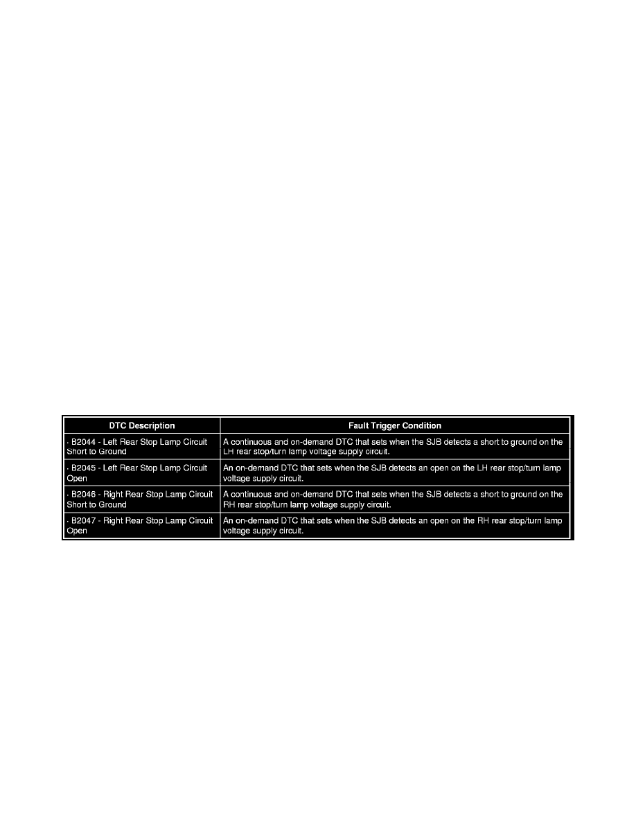
B2044-B2047
This pinpoint test is intended to diagnose the following:
-
Fuse
-
Wiring, terminals or connectors
-
Rear lamp assembly
-
Rear lamp jumper harness
-
High mounted stoplamp
-
SJB
PINPOINT TEST J: ONE OR MORE STOPLAMPS ARE INOPERATIVE
NOTICE: Use the correct probe adapter(s) when making measurements. Failure to use the correct probe adapter(s) may damage the
connector.
NOTE: Make sure the bulb is good before continuing diagnostics.
NOTE: Failure to disconnect the battery when instructed will result in false resistance readings. Refer to Battery.