
Taurus X AWD V6-3.5L (2009)
on the puddle lamp output circuit. This DTC also sets as a result when the SJB fuse 10 (15A) has failed or is removed.
This pinpoint test is intended to diagnose the following:
-
Fuse
-
Wiring, terminals or connectors
-
Exterior mirror
-
Puddle lamp
-
SJB
PINPOINT TEST G: THE PUDDLE LAMP(S) ARE INOPERATIVE
NOTICE: Use the correct probe adapter(s) when making measurements. Failure to use the correct probe adapter(s) may damage the
connector.
-------------------------------------------------
G1 CHECK THE PUDDLE LAMP OPERATION
-
Open any door and observe the puddle lamps.
-
Are both the puddle lamps inoperative?
Yes
GO to G2.
No
GO to G3.
-------------------------------------------------
G2 CHECK CIRCUIT CLN25 (VT) FOR AN OPEN
-
Ignition OFF.
-
Disconnect: SJB C2280c.
-
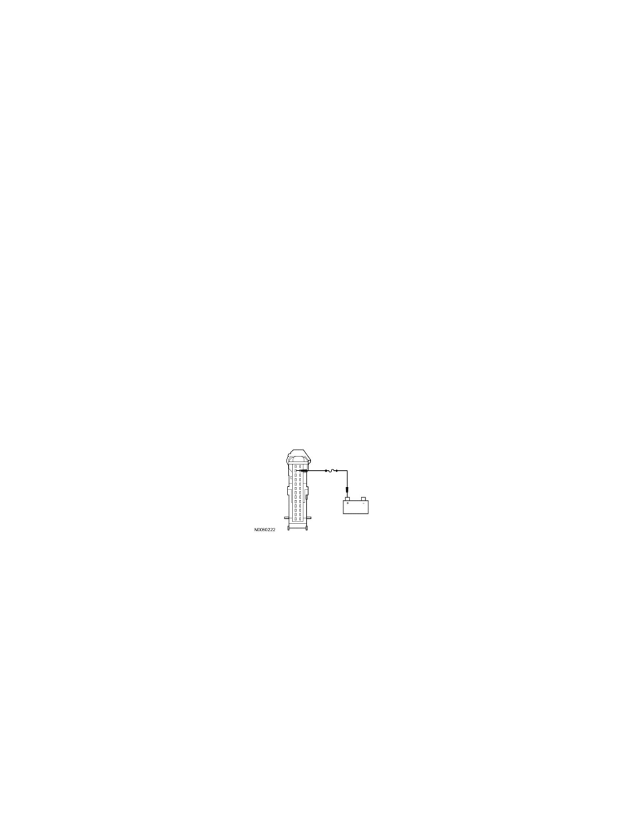
NOTE: If the fuse fails, Refer to the Wiring Diagrams to identify the possible causes of the short to ground on circuit CLN25 (VT).
-
Connect a fused jumper wire between the SJB C2280c-12, circuit CLN25 (VT), harness side and battery positive.
-
Do the puddle lamps illuminate?
Yes
REMOVE the jumper wire. GO to G5.
No
REMOVE the jumper wire. REPAIR the circuit. RUN the on-demand self-test (required to clear certain DTCs). CORRECT any unresolved DTCs.
CLEAR all DTCs. TEST the system for normal operation.
-------------------------------------------------
G3 CHECK THE EXTERIOR MIRROR
NOTE: Make sure the suspect puddle lamp bulb is OK before continuing diagnostics.
-
Disconnect: Suspect Exterior Mirror.
-
NOTE: The courtesy lamps must be active during this test.
-
Open any door.
-
Measure the voltage between the LH exterior mirror C516-5, circuit CLN25 (VT), harness side and the LH exterior mirror C516-7, circuit GD133
(BK), harness side; or between the RH exterior mirror C625-7, circuit CLN25 (VT), harness side and the RH exterior mirror C625-7, circuit