
Taurus X AWD V6-3.5L (2009)
GD148 (BK/YE), harness side.
-
Is the voltage greater than 10 volts?
Yes
INSTALL a new exterior mirror in question. TEST the system for normal operation.
No
GO to G4.
-------------------------------------------------
G4 CHECK CIRCUIT CLN25 (VT) FOR AN OPEN (INDIVIDUAL PUDDLE LAMP INOPERATIVE)
-
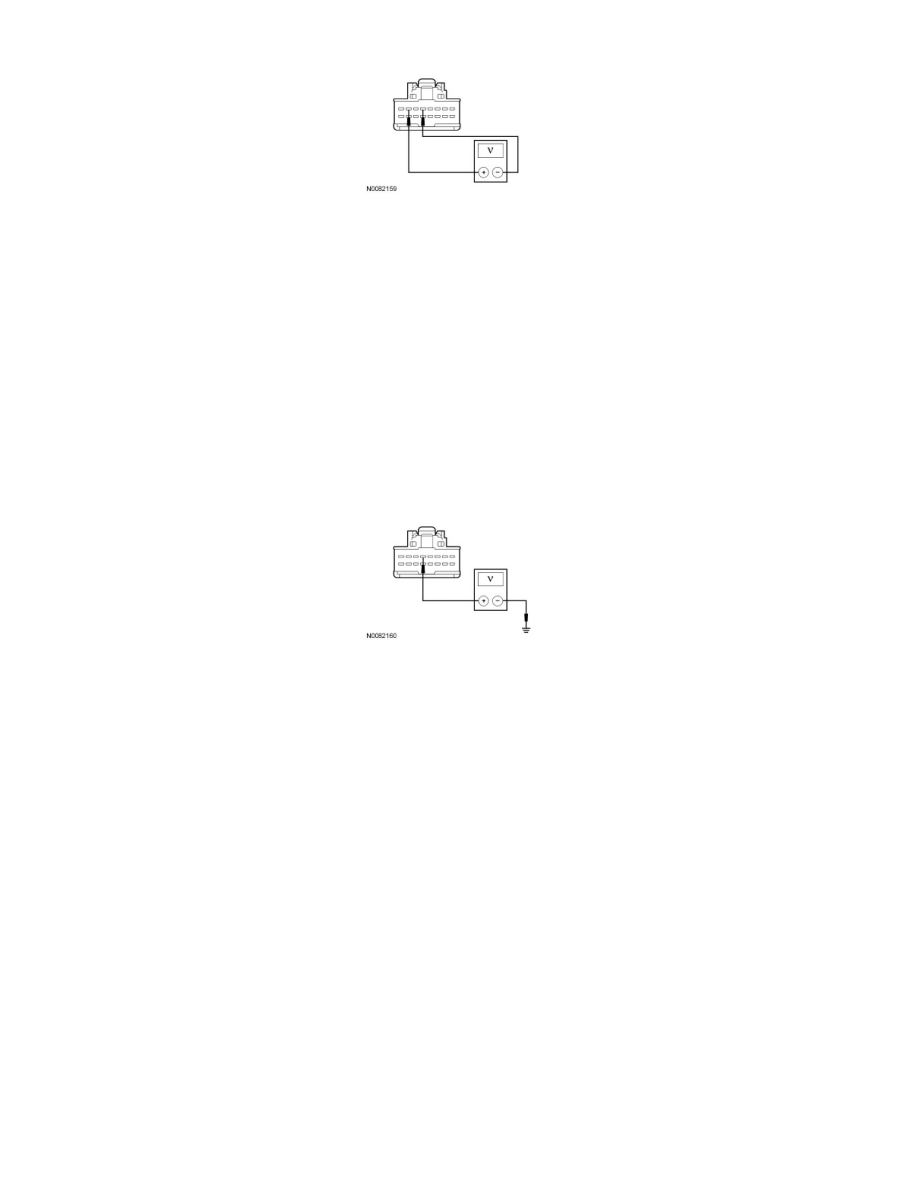
NOTE: The courtesy lamps must be active during this test.
-
Open any door.
-
Measure the voltage between the LH exterior mirror connector C516-5, circuit CLN25 (VT), harness side and ground; or between the RH exterior
mirror connector C625-5, circuit CLN25 (VT), harness side and ground.
-
Is the voltage greater than 10 volts?
Yes
For the LH exterior mirror, REPAIR circuit GD133 (BK) for an open. TEST the system for normal operation.
For the RH exterior mirror, REPAIR circuit GD148 (BK/YE) for an open. TEST the system for normal operation.
No
REPAIR circuit CLN25 (VT) for an open. TEST the system for normal operation.
-------------------------------------------------
G5 CHECK FOR CORRECT SJB OPERATION
-
Disconnect all the SJB connectors.
-
Check for:
-
corrosion
-
damaged pins
-
pushed-out pins
-
Connect all the SJB connectors and make sure they seat correctly.
-
Operate the system and verify the concern is still present.
-
Is the concern still present?
Yes
INSTALL a new SJB. TEST the system for normal operation.
No