
Taurus X AWD V6-3.5L (2009)
-
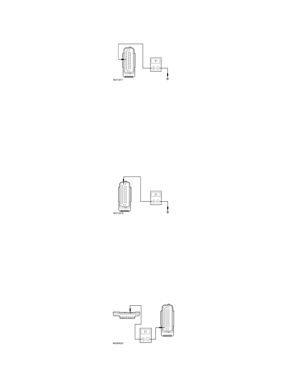
Ignition OFF.
-
Disconnect: ABS Module C135.
-
Ignition ON.
-
Measure the voltage between the ABS module C135-32, circuit CBB38 (GY/BU), harness side and ground.
-
Is the voltage greater than 10 volts?
Yes
GO to B2.
No
VERIFY the Battery Junction Box (BJB) fuse 38 (10A) is OK. If OK, REPAIR the circuit. If not OK, Refer to the Wiring Diagrams to identify the
possible causes of the short circuit. CLEAR the DTCs. REPEAT the network test with the scan tool.
-------------------------------------------------
B2 CHECK THE GROUND CIRCUIT FOR AN OPEN
-
Ignition OFF.
-
Measure the resistance between the ABS module C135-38, circuit GD120 (BK/GN), harness side and ground.
-
Is the resistance less than 5 ohms?
Yes
GO to B3.
No
REPAIR the circuit. CLEAR the DTCs. REPEAT the network test with the scan tool.
-------------------------------------------------
B3 CHECK THE HS-CAN CIRCUITS BETWEEN THE DLC AND THE ABS MODULE FOR AN OPEN
-
Measure the resistance between the ABS module C135-26, circuit VDB04 (WH/BU), harness side and the DLC C251-6, circuit VDB04
(WH/BU), harness side.
-
Measure the resistance between the ABS module C135-14, circuit VDB05 (WH), harness side and the DLC C251-14, circuit VDB05 (WH),