
Taurus X AWD V6-3.5L (2009)
-
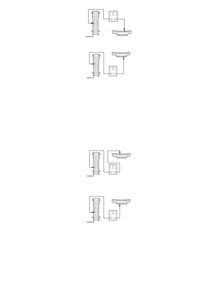
Measure the resistance between the IC C220-8, circuit VDB05 (WH), harness side and the DLC C251-14, circuit VDB05 (WH), harness side.
-
Are the resistances less than 5 ohms?
Yes
GO to C5.
No
REPAIR the circuit in question. CLEAR the DTCs. REPEAT the network test with the scan tool.
-------------------------------------------------
C5 CHECK THE MS-CAN CIRCUITS BETWEEN THE IC AND THE DLC FOR AN OPEN
-
Measure the resistance between the IC C220-4, circuit VDB06 (GY/OG), harness side and the DLC C251-3, circuit VDB06 (GY/OG), harness
side.
-
Measure the resistance between the IC C220-5, circuit VDB07 (VT/OG), harness side and the DLC C251-11, circuit VDB07 (VT/OG), harness
side.
-
Are the resistances less than 5 ohms?
Yes
GO to C6.
No
REPAIR the circuit in question. CLEAR the DTCs. REPEAT the network test with the scan tool.
-------------------------------------------------