
Taurus X AWD V6-3.5L (2009)
-------------------------------------------------
E3 CHECK THE RCM CASE GROUND
-
Ignition OFF.
-
Measure the resistance between the RCM case and a good chassis ground.
-
Is the resistance less than 5 ohms?
Yes
GO to E4.
No
REPAIR the RCM case ground as necessary. REPOWER the SRS. REFER to Air Bag Systems. CLEAR the DTCs. REPEAT the network test with the
scan tool.
-------------------------------------------------
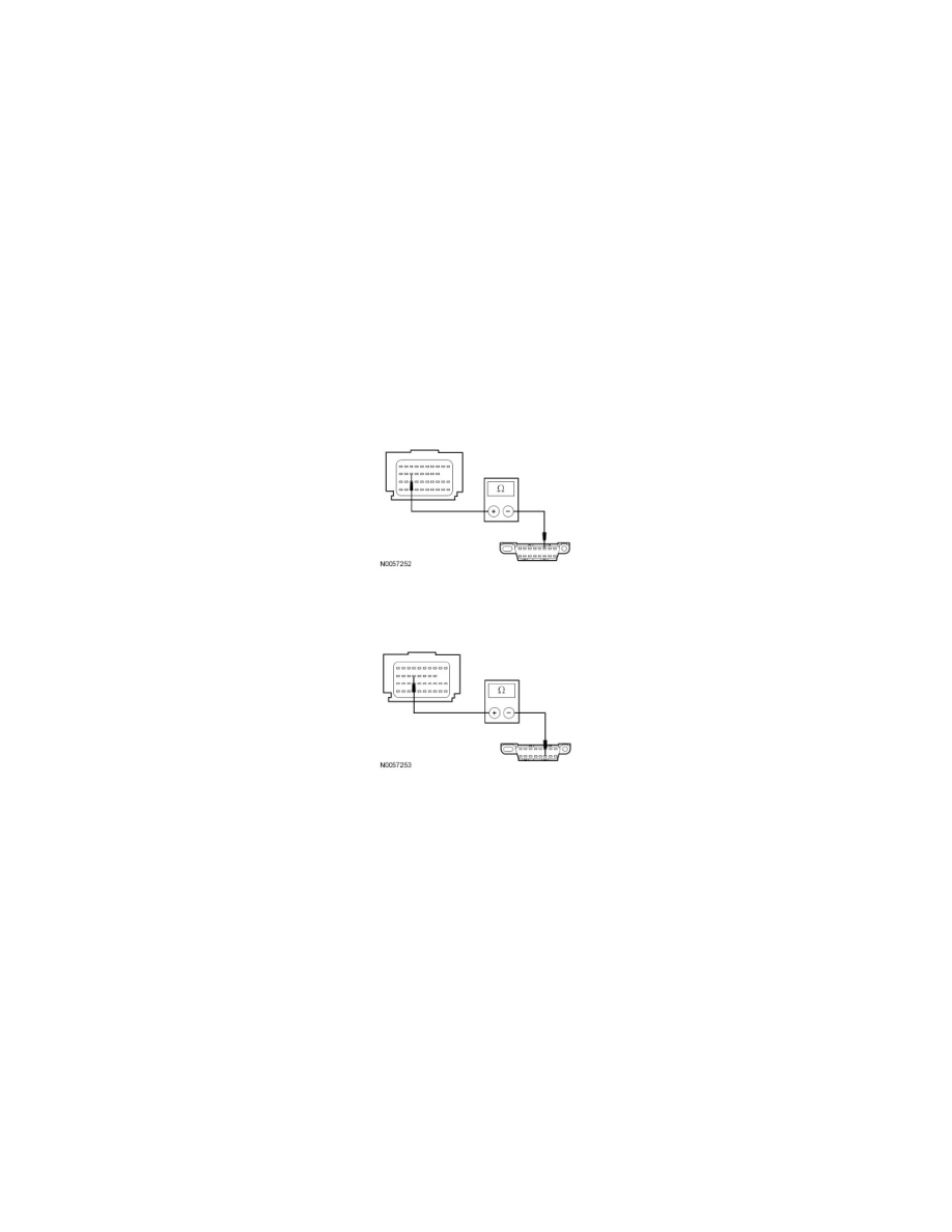
E4 CHECK THE HIGH SPEED CAN CIRCUITS BETWEEN THE RCM AND THE DATA LINK CONNECTOR (DLC) FOR AN OPEN
-
Measure the resistance between the RCM C310b-18, circuit VDB04 (WH/BU), harness side and the DLC C251-6, circuit VDB04 (WH/BU),
harness side.
-
Measure the resistance between the RCM C310b-17, circuit VDB05 (WH), harness side and the DLC C251-14, circuit VDB05 (WH), harness
side.
-
Are the resistances less than 5 ohms?
Yes
GO to E5.
No
REPAIR the circuit in question. REPOWER the SRS. REFER to Air Bag Systems. CLEAR the DTCs.
REPEAT the network test with the scan tool.
-------------------------------------------------
E5 CHECK FOR CORRECT RCM OPERATION
-
Disconnect all the RCM connectors.
-
Check for:
-
corrosion
-
damaged pins
-
pushed-out pins
-
Connect all the RCM connectors and make sure they seat correctly.
-
Operate the system and verify the concern is still present.
-
Is the concern still present?