
Taurus X AWD V6-3.5L (2009)
Drive/Propeller Shaft: Procedures
Driveline Angle Measurement
Driveline Angle Measurement
NOTE: This procedure does not apply to CV joints, flex couplers or double cardan joints that are used in some driveshafts. This check is for
single-cross and roller-style joints found in the driveshafts.
NOTE: Prior to checking driveline angularity, inspect the U-joints for correct operation.
NOTE: An incorrect driveline angle can cause a vibration or shudder.
NOTE: Driveline angularity is the angular relationship between the engine crankshaft, the driveshaft and the rear axle pinion. Factors determining
driveline angularity include ride height, rear spring and engine mounts.
All vehicles
1. Carry out the following preliminary setup steps:
-
Inspect the U-joints for correct operation.
-
Park the vehicle on a level surface such as a drive-on hoist, or back onto a front end alignment rack.
-
Verify the curb position ride height is within specifications with the vehicle unloaded and all of the tires are inflated to their normal operating
pressures.
-
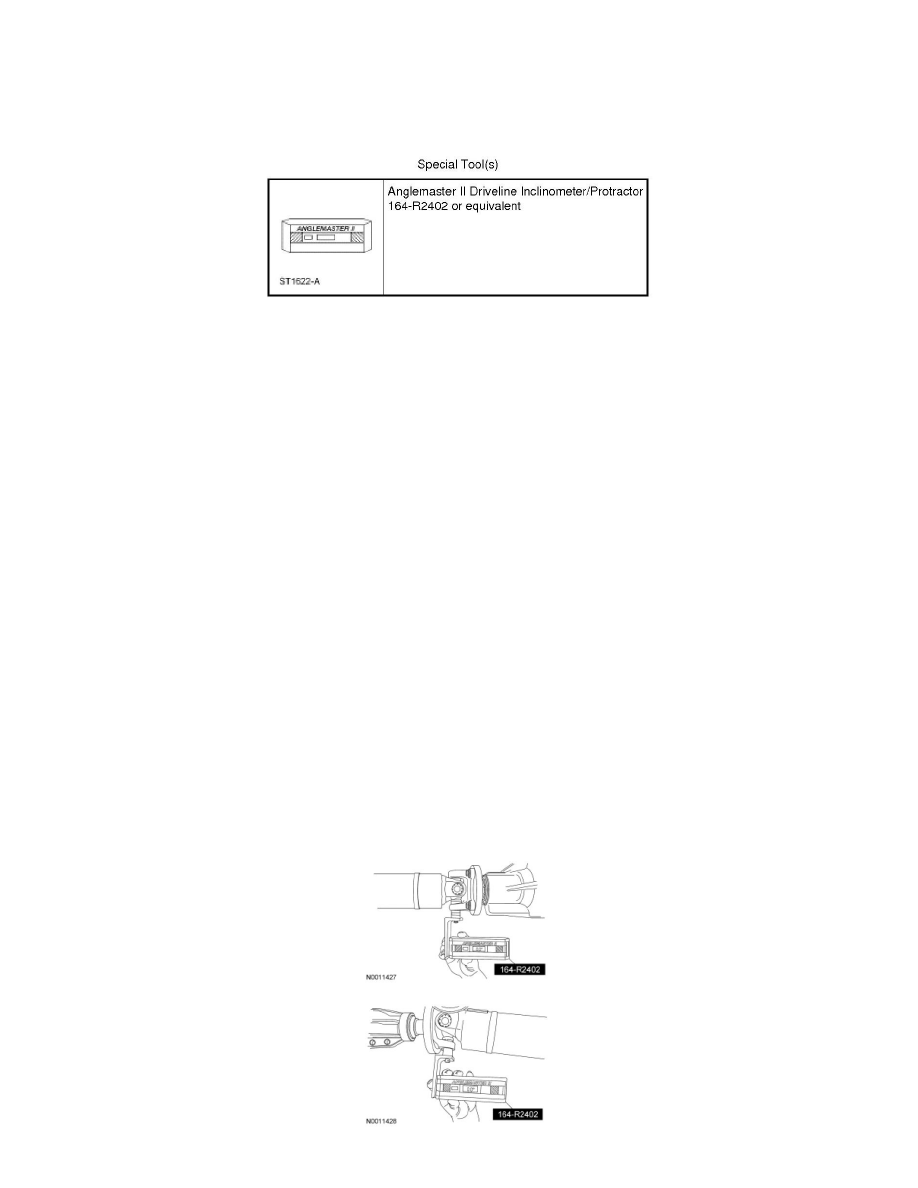
Calibrate the Anglemaster II Driveline Inclinometer/Protractor by placing it on a clean, flat level of the frame rail and press the ALT-ZERO
button.
Vehicles with flat-flanged, split-pin or slip-flanged U-joints
2. NOTE: If equipped, remove the snap ring to allow access to the base of the U-joint cup. Make sure the Anglemaster II Driveline
Inclinometer/Protractor is seated against the U-joint cup.
NOTE: Rotate the driveshaft until the flange U-joint cup is parallel with the floor. This will simplify taking measurements.
To check the U-joint operating angle, install the Anglemaster II Driveline Inclinometer/Protractor. Check and record the flange angle as angle A.