
Tempo L4-122 2.0L DSL (1984)
SPECIAL SERVICE TOOLS
Tool Number
Description
T63L-8620-A or
Belt Tension Gauge
021-00019
021-00028
Belt Tension Gauge - Offset
Description and Operation
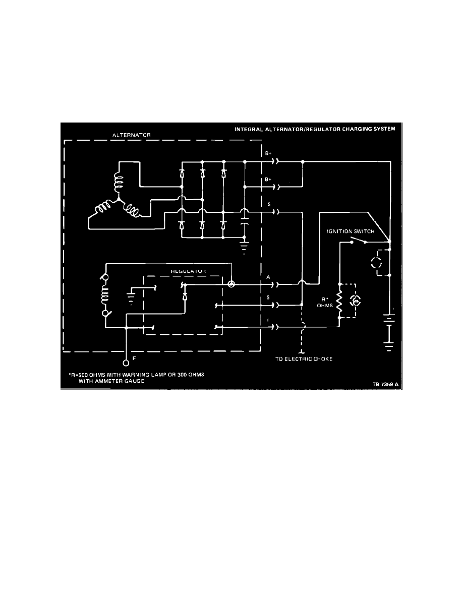
Figure 6
The alternator is belt driven from the engine. Field current is supplied from the alternator regulator, mounted on the rear of the alternator, to the rotating
field of the alternator through two brushes and two slip rings (Figure 6).
The alternator produces power in the form of alternating current. The alternating current is rectified to direct current by six diodes. The alternator
regulator automatically adjusts the alternator field current to maintain the alternator output voltage within prescribed limits to correctly charge the battery
. The alternator is selfcurrent limiting.
The regulator voltage control circuit is turned on when the ignition switch is ON and voltage is applied to the regulator I terminal through a resistor in
the I circuit. When the ignition switch is OFF, the control circuit is turned off and no field current flows to the alternator.
On warning lamp equipped vehicles, the warning lamp is connected across the terminals of a 500 ohm resistor at the instrument cluster. Current passes
through the warning lamp when the ignition switch is in the RUN position and there is no voltage at terminal S. When voltage at S rises to a pre-set
value, the regulator switching circuits stop and flow of current into terminal I and the lamp turns OFF.
System voltage is "sensed" and alternator field current is drawn through terminal A. The regulator switching circuits will turn the warning lamp ON,
indicating a system fault, if terminal A voltage is excessively high or low, or if the terminal S voltage signal is abnormal.
A fuse link is included in the charging system wiring on all models. The fuse link is used to prevent damage to the wiring harness and alternator if the
wiring harness should become grounded, or if a booster battery is connected to the charging system with the wrong polarity.