
Tempo L4-122 2.0L DSL (1984)
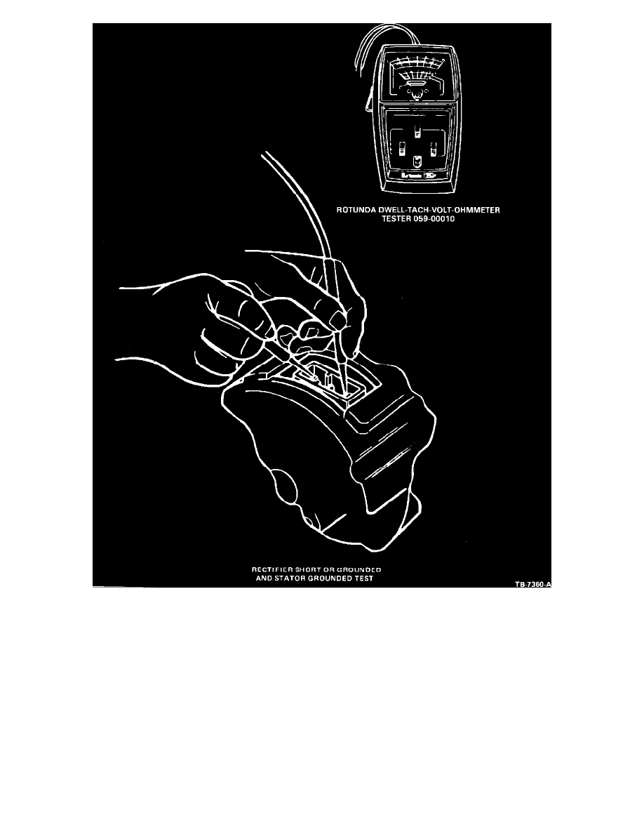
Figure 7
1.
Contact one ohmmeter probe to one of the alternator B+ blade terminals and the other probe to the STA blade terminal (Figure
7). Then, reverse the ohmmeter probes and repeat the test. Normally, there will be no needle movement in one direction,
indicating the rectifier diodes are being checked in the reverse current direction and are not shorted. A low reading of about
(6.5) ohms with the probes reversed indicates that rectifier positive diodes are being checked in the forward current direction.
A low reading in both directions indicates a bad positive diode or shorted radio suppression capacitor. The radio suppression
capacitor is built into the rectifier assembly and is not individually serviceable.
2.
Perform the same test using the STA blade terminal and alternator rear housing. A reading in both directions indicates either a
grounded stator winding, a bad negative diode, a grounded stator lead wire or a shorted radio suppression capacitor.
3.
If there is no needle movement with the probes in one direction and no needle movement or high resistance (significantly over
(6.5) ohms) in the opposite direction for Tests 1 and 2, a bad connection exists in the rectifier assembly.
Field Open or Shorted Circuit Test
This test is performed with an ohmmeter (Tool 059- 00010 or equivalent).