
Tempo L4-140 2.3L CFI (1985)
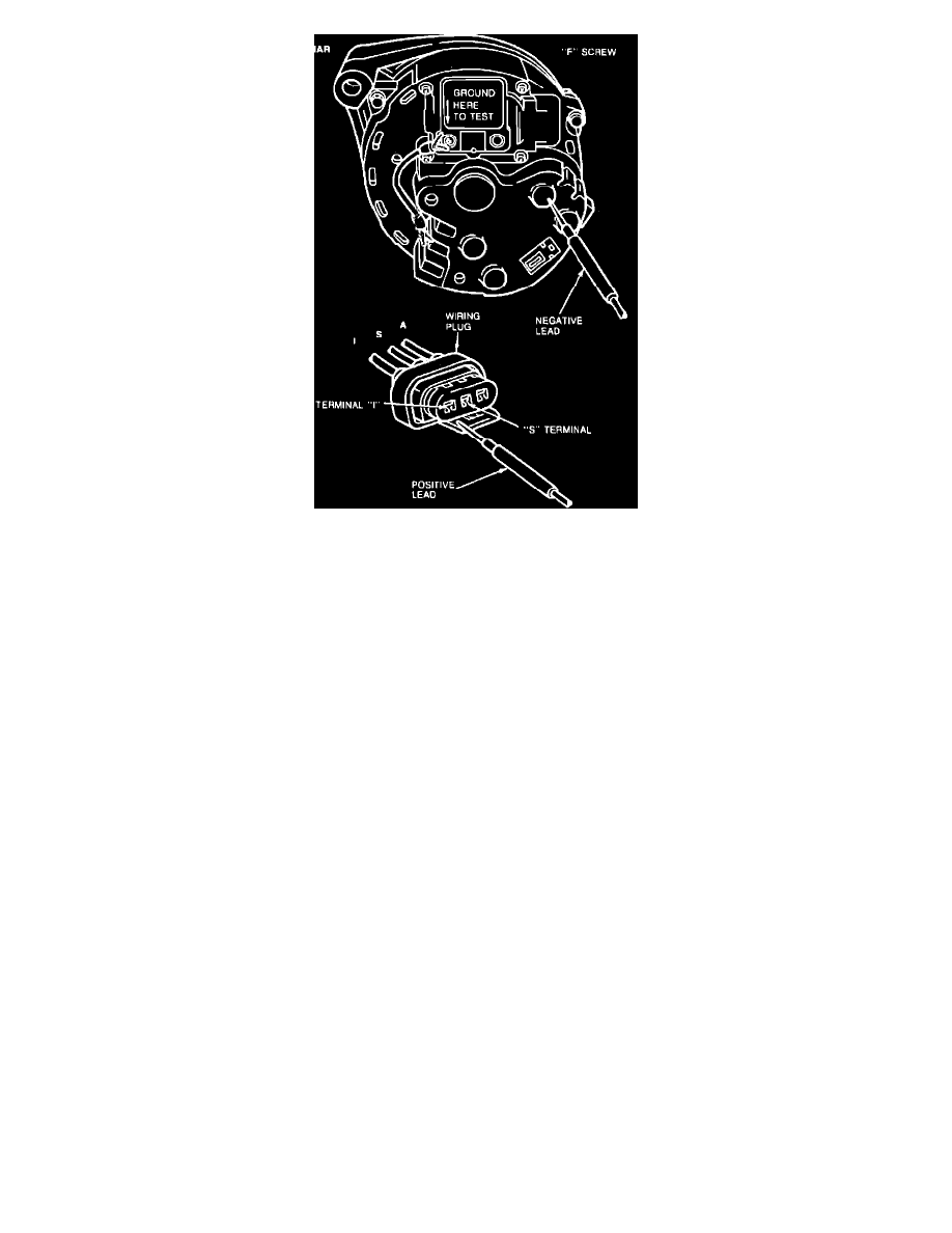
Fig. 13 Testing regulator S and/or I circuit. Integral Alternator Regulator (IAR)
Alternators W/Integral Regulator
1.
Disconnect electrical connector from regulator. Connect a jumper wire from the regulator A lead to connector plug A lead. Add a jumper wire
from the regulator F screw to the alternator rear housing.Fig. 13.
2.
With engine idling and voltmeter negative lead connected to alternator rear housing, connect voltmeter positive lead to S terminal and then to I
terminal of regulator electrical connector. Voltage at S circuit should read approximately one-half of the I circuit. If voltage readings are normal,
remove jumper wire. Replace regulator and connect electrical connector to regulator.
3.
If no voltage is present, remove jumper wires and service faulty circuit or alternator.
4.
Connect voltmeter positive lead to positive battery terminal.
5.
Connect electrical connector to regulator and replace bulb, if equipped.