
Tempo L4-140 2.3L HSC (1986)
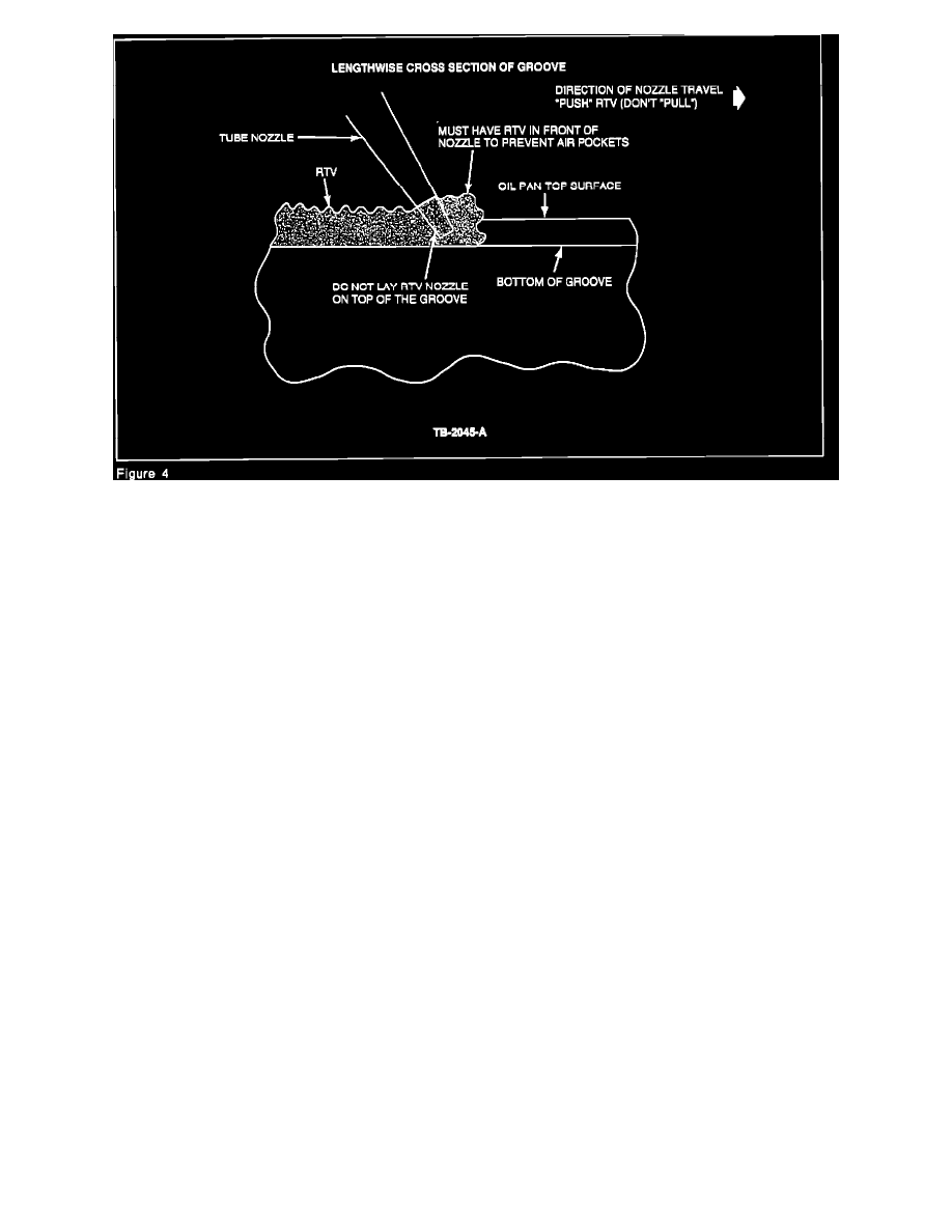
Figure 4
12.
Apply enough RTV (F1AZ-19562-A) in the oil pan to completely fill the oil pan groove, regardless of the groove size or configuration, Figures 3
and 4.
^
Have a bead about 0.2" (5 mm) wide by 0.25" (6 mm) high, above the pan surfaces, in both front and rear half-rounds, Figures 2 and 3.
^
Have a bead about 0.2" (5 mm) wide by 0.15" (4 mm) high, above the oil pan surfaces, along the rails, Figures 2 and 3.
NOTE: BE SURE THAT THE GROOVE IS COMPLETELY FILLED WITH RTV. MAKE CERTAIN THAT NO AIR IS TRAPPED IN THE
GROOVE BECAUSE A BLOW OUT OF THE RTV MAY OCCUR WHEN THE ENGINE IS HEATED UP DURING NORMAL ENGINE
OPERATIONS.
^
Have the nozzle of the RTV tube slightly above the oil pan groove.
^
Apply enough RTV to build up the bead above the oil pan surface before moving the nozzle along the groove.
^
Do not lay the RTV nozzle on top of the groove because this may leave air pockets, especially in oil pans with deep grooves, Figure 4.
CAUTION: APPLYING RTV IN EXCESS OF THE SPECIFIED AMOUNT WILL NOT IMPROVE THE SEALING OF THE OIL PAN. IT COULD
CAUSE THE OIL PICK-UP SCREEN TO BECOME PLUGGED WITH PIECES OF RTV.
13.
Immediately, within 5 minutes of applying the RTV to the oil pan, install the oil pan against the cylinder block to prevent the RTV from skinning
over. Tighten the oil pan bolts as follows:
a.
Tighten the oil pan to transaxle bolts to 30-39 lb-ft (40-54 N-m).
b.
Loosen the oil pan to transaxle bolts 1/2 turn.
c.
Tighten the oil pan flange bolts to 15-22 lb-ft (20-30 N-m). Start in the center of the oil pan and work to the rear of the engine. Then, tighten
the bolts from the center to the front of the engine.
d.
Tighten the oil pan to transaxle bolts to 30-39 lb-ft (40-54 N-m).
14.
Install the bracket from the air conditioning compressor line above the oil pan.
15.
Install the bracket at the block and install the water pump inlet tube assembly.
16.
Install the starter motor.
17.
Install the thermactor (MTA) tubes and connect the rubber hose at the check valve.