
Tempo L4-140 2.3L HSC (1986)
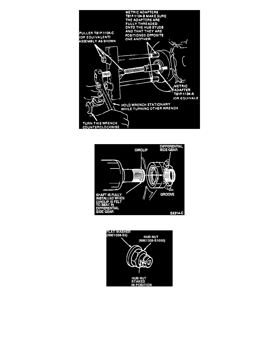
Fig. 3 Separating outer constant velocity joint from hub
Installing Shaft
Fig. 5 Hub nut staking tool fabrication
5.
Separate ball joint from steering knuckle using pry bar, Fig. 1. Lower ball joints fit into a pocket formed in the plastic disc brake shield. The
shield must be positioned away from the ball joint while removing ball joint from steering knuckle.
6.
Remove halfshaft from differential housing using suitable pry bar. Use caution not to damage dust deflector located between shaft and case, Fig. 2.
If an automatic transaxle halfshaft assembly cannot be removed from differential by using a pry bar, insert a large bladed screwdriver between
differential pinion shaft and inboard constant velocity joint stub shaft. Sharply tap on screwdriver handle, to free halfshaft from differential. Use
caution not to damage differential oil seal, constant velocity joint boot or constant velocity joint dust deflector.
7.
Separate outer constant velocity joint from hub using puller T81P-1104C or equivalent, Fig. 3, and adapters T81P-1104B and T81P-1104A or
equivalent. Do not use a hammer to separate outboard constant velocity joint stub shaft from hub as damage to internal components may
result.