
Tempo V6-182 3.0L (1993)
does not contact or is slow to contact the limit switch plunger, resulting in a "stall" condition eventually resulting in drive belt damage.
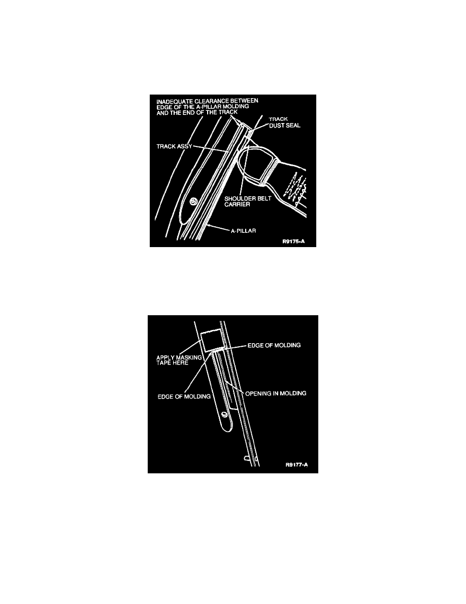
21. Install only the A-pillar interior trim molding, in order to check for possible interference between the shoulder belt track dust seals and the end of
the drive belt. This interference may be caused by a mispositioned instrument panel and loran A-pillar interior trim molding, resulting in the limit
switch plunger not being depressed and eventual drive belt damage.
22. Perform the Voltage at the Motor Test procedure. See: Testing and Inspection/Component Tests and General Diagnostics/Passive Restraint
System (Motorized Seat Belts)
23. If voltage is being supplied to the motor when the belt carrier is at the A-pillar, remove the A-pillar molding and re-test for voltage.
24. If voltage is interrupted with the A-pillar molding removed, the molding must be reworked as follows:
a. Install the A-pillar molding to the A-pillar.
b. Measure the distance from the edge of the metal track to the edge of the molding.
25. Determine the exact area to be reworked as follows:
-
If the distance is greater than 17 mm, the molding does not require rework.
-
If the distance is less than 17 mm, the molding must be reworked. Proceed to Step 26.
26. Apply a piece of masking tape to the molding.
27. Measure from the edge of the metal track 17 mm, and at the approximate center of the opening in the molding, mark the tape.