
Tempo V6-182 3.0L (1993)
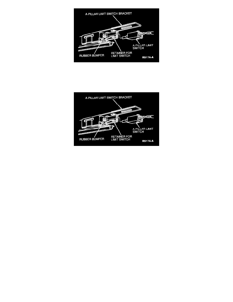
3. Install the A-pillar limit switch to the switch bracket/track assembly. Make sure the rubber limit switch bumper is installed correctly and the switch
plunger passes freely through the plunger and the plunger opening in the bracket.
NOTE: Remove the screws retaining the limit switch bracket to the track assembly and apply Threadlocker and Sealer EOAZ-19554-AA
(ESE-M4G204-A) or equivalent to the threads. Install the screws.
4. Loosely install the shoulder belt track to the body.
5. Install the existing B-pillar limit switch to the track assembly. Make sure the rubber limit switch bumper is installed correctly and that the switch
plunger passes freely through the bumper and the opening in the mounting bracket.
6. Secure the limit switch wiring to the B-pillar support bracket with a new adjustable bundling strap.
7. Tighten the two B-pillar rear support bracket retaining bolts to 23-33 Nm (17-24 lb-ft).
8. Tighten the two overhead track to body retaining screws.
9. Install the limit switch bracket to the A-pillar.
10. Insert the drive belt through the vertical guide and the motor guide. Connect the guide to the B-pillar rear support bracket.
11. Connect the motor guide to the vertical guide (if the guide was replaced).
12. Align the slots in the drive belt with the teeth on the motor drive gear. Position the guide to the motor.
NOTE: Prior to installing the retaining screws, make sure there is no binding of the drive belt at the motor.
13. Apply Threadlocker and Sealer EOAZ-19554-AA (ESE-M4G204-A) or equivalent to the threads of the two motor guide retaining screws. Install
and tighten the screws to 2.5-4.0 Nm (22-35 lb-in).
14. Install the vertical guide retaining screws.
15. Install the lower guide to the motor guide.
16. Cycle the shoulder belt carrier in both directions.
CAUTION: If the shoulder belt track assembly is being installed after the replacement of the drive belt, the following steps must be performed or
the replacement drive belt may eventually be damaged.
17. Install only the A-pillar interior trim molding.
18. Perform the Voltage at the Motor Test. See: Testing and Inspection/Component Tests and General Diagnostics/Passive Restraint System
(Motorized Seat Belts)
19. Prior to installing the shoulder belt track assembly in the vehicle, perform the Lock-out Switch Test.
20. After installing the shoulder belt track assembly, make sure the ends of the dust seals are straightened.
CAUTION: If the instrument panel was installed too high on one side during production, and/or the A-pillar molding was mispositioned too high,
this may cause the molding to push the ends of the dust seals upward into the path of the drive belt. As a result of this obstruction, the shoulder belt
does not contact or is slow to contact the limit switch plunger, resulting in a "stall" condition eventually resulting in drive belt damage.
21. Install only the A-pillar interior trim molding, in order to check for possible interference between the shoulder belt track dust seals and the end of