
Thunderbird V6-232 3.8L (1982)
Choke Pull-off: Adjustments
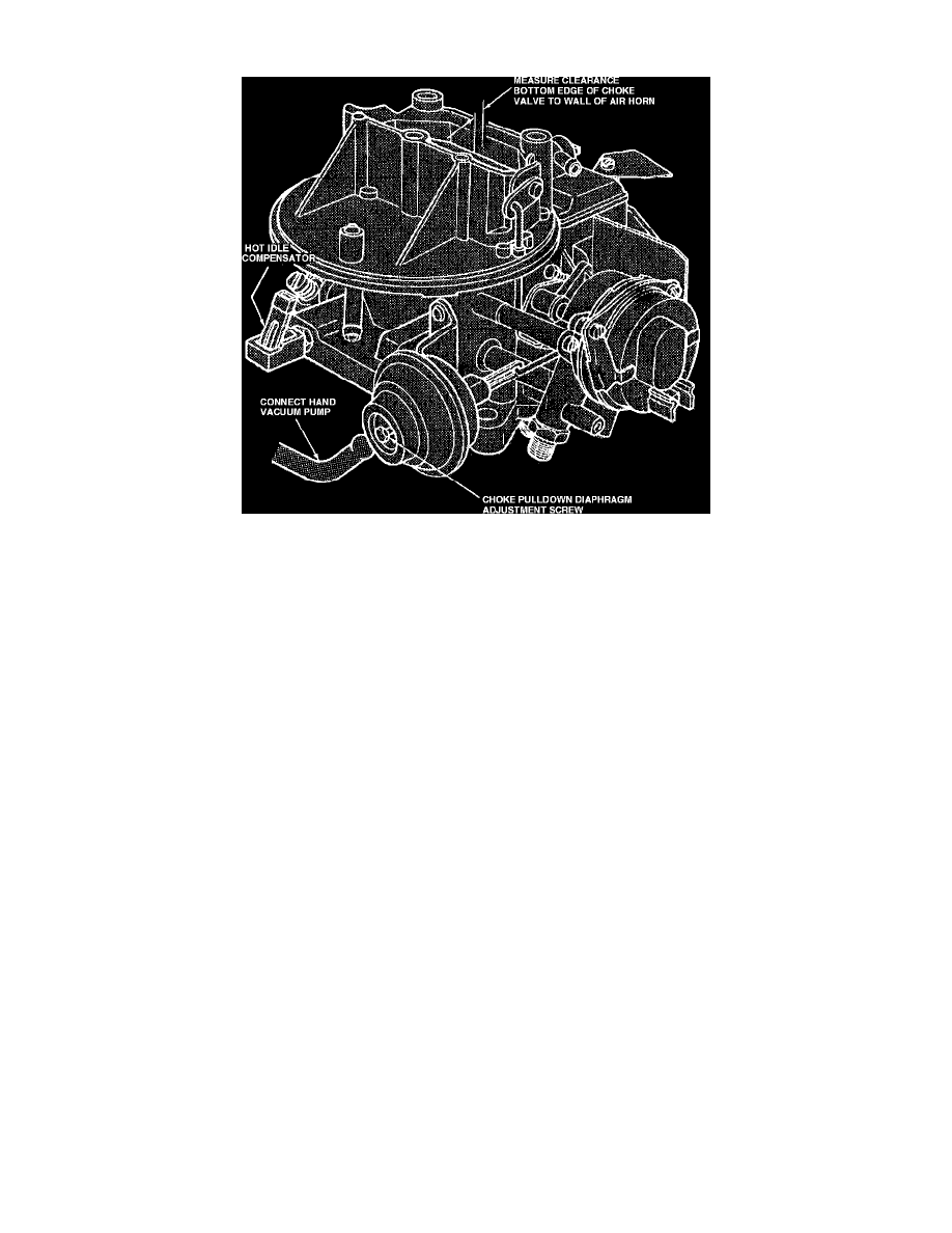
Fig. 5 Choke plate pulldown adjustment (Typical)
CAUTION: Do not attempt to turn the diaphragm adjusting screw without first loosening the Loctite which has been applied to the threads of the screw.
The Loctite can be softened by heating the area around the screw with an electric soldering gun or by applying Loctite to the screw. When the Loctite
has softened enough, the screw can be turned without causing any damage.
1. Remove carburetor from engine, then using a suitable punch, center punch choke retaining cap screw heads.
2. Using a 1/4 inch drill bit, drill screw heads deep enough to remove retainer from cap, then remove choke cap by inserting a flat chisel between cap
and gasket.
3. Remove remaining portion of choke cap retaining screws using pliers. Also clean epoxy sealer and gasket from choke cap and housing mating
surfaces.
4. Rotate choke thermostatic housing to lightly close choke plate, then rotate housing an additional 90 degrees.
5. Using the edge of a file, file a 1/8 inch deep groove on pulldown motor tamper resistance cover 1/4 inch from rear edge of pulldown motor.
NOTE: A tamper resistance cover is not used on the pulldown motor.
6. Using a suitable awl inserted in filed groove, carefully tap plug from pulldown motor.
7. Activate pulldown motor using an external vacuum source or by manually forcing the diaphragm to the retracted position.
8. Using a drill bit of the specified size, measure clearance between choke plate and carburetor air horn wall, Fig. 5
9. Loosen pulldown motor adjusting screw as described in CAUTION, then remove adjusting screw and clean remaining thread locking compound.
10. Reinstall adjusting screw and adjust. Rotate adjusting screw clockwise to decrease pulldown and counterclockwise to increase pulldown.
11. After completing adjustment, use Loctite 240 or equivalent to lock adjusting screw in position, then tap tamper resistance cover into place on
pulldown motor. Apply epoxy sealer MT13 or equivalent to edge and groove on cover.
NOTE: After completing choke plate clearance adjustment, leave choke thermostatic housing in the full rich position and check fast idle cam
setting as described under Fast Idle Cam Position Adjustment.