
Thunderbird V6-232 3.8L SC (1989)
Valve Clearance: Adjustments
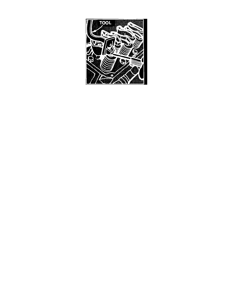
Fig. 5 Compressing Lifter To Check Valve Clearance
Correct valve clearance is .09-.19 inch.
A .060 inch longer or a .060 inch shorter pushrod is available to compensate for dimensional changes in the valve train. If clearance is less than
specified, the .060 inch shorter pushrod should be used. If clearance is more than the maximum specified, the .060 inch longer pushrod should be used.
Using an auxiliary starter switch crankshaft until No. 1 cylinder is at TDC compression stroke, then compress valve lifter using tool T82C-6500-A or
equivalent, Fig. 5. At this point, the following valves can be checked: intake Nos. 1, 3 and 6; exhaust Nos. 1, 2 and 4.
After clearance on these valves has been checked, rotate crankshaft until No. 5 cylinder is at TDC compression stroke (1 revolution of crankshaft), and
then compress valve lifter using tool No. T82C-6500-A or equivalent, Fig. 5, and check the following valves: intake Nos. 2, 4 and 5; exhaust Nos. 3, 5
and 6.