
Thunderbird V6-232 3.8L SC (1989)
2.
Apply power to pin (B). The test lamp should not light.
3.
Apply power to pin S. The heated rear window symbol on the switch knob should light up.
4.
Momentarily actuate rocker knob to the ON position. The test lamp should come on andstay on after rocker knob returns to othe normal position.
5.
Test lamp should go off under any one or more of the following conditions:
a.
If rocker knob is moved to the OFF position.
b.
Jumper wire between pins I and B is removed.
c.
Approximately 10 minutes have elapsed.
Grid Wire Test
1.
Using a strong lamp inside the vehicle, visually inspect the wire grid from the outside. A broken grid wire will appear as a brown spot.
2.
Run the engine at idle. Set the control switch to ON. The indicator lamp should come on.
3.
Working inside the vehicle with a 12-volt DC voltmeter such as Rotunda Digital Volt Ohm Meter 007-00001 or equivalent, contact the broad
red-brown strips of the rear window positive lead to battery side and negative lead to ground side. The meter should read 10-13 volts. A lower
voltage reading indicates a loose ground wire (pigtail) connection at the ground attaching screw.
4.
Contact a good ground point with the negative lead of the meter. The voltage reading should not change.
5.
With the negative lead of the meter grounded, touch each grid line of the heated rear window at its midpoint with the positive lead. A reading of
approximately 6-volts indicates that the line is good. A reading of 0-volts indicates that the line is broken between the midpoint and the B+ side of
the grid line. A reading of 12-volts indicates that the circuit is broken between the midpoint of the grid line and ground.
REMOVAL AND INSTALLATION
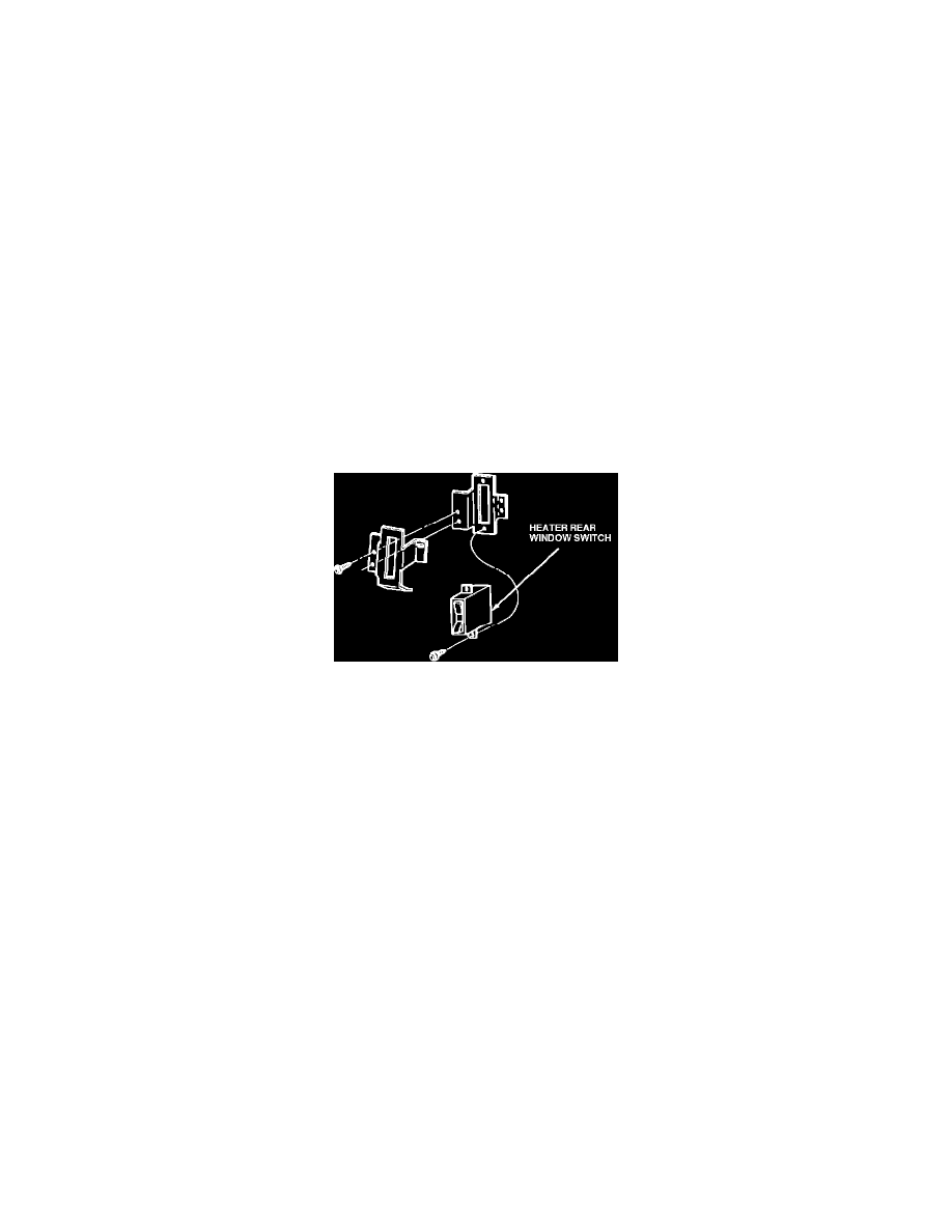
Control Assembly Removal and Installation
1.
Remove applique.
2.
Remove two screws retaining control assembly.
3.
To install, reverse Steps 1 and 2.
Window Disconnect wire leads at each end of the glass. Remove window. Refer to Section 43-11.
1989 Mark VII
36-86-3
Window, Rear-Defroster
36-86-3
MAJOR SERVICE OPERATIONS
Grid Wire Repair
NOTE:
A single break or any breaks that total more than 25 mm (1 inch) in one grid cannot be repaired. The window must be replaced. For breaks less
than 25 mm (1 inch) long, use the following procedure:
NOTE:
If the first layer of the heated rear window grid (brown color) is damaged or missing, it will be necessary to apply brown Acrylic Lacquer
Touch-Up Paint AL81-5477-B (ESR-M2P100-B) or equivalent on the glass prior to applying the Ford Rear Window Defroster Repair
D8AZ-19562-AA (ESB-M4J58-A) or equivalent. Inoperative grid wires on heated rear windows should be repaired by using Ford Rear
Window Defroster Repair D8AZ-19562-AA (ESB-M4J58-A) or equivalent.
Surface Preparation
1.
The vehicle should be brought inside and permitted to come to room temperature of 16~C (60~F) or above.
2.
Clean the entire grid line service area with Ultra Clear Spray Glass Cleaner D4AZ-19C507-AA (ESRM14P5-A) or equivalent to remove all dirt,
wax, grease, oil or other foreign matter. It is important that the repair area be clean and dry.
CAUTION: Do not use scrapers, sharp instruments, or abrasive cleaners on the interior surface of the rear window, as this may cause damage to
the grid lines.