
Thunderbird V8-281 4.6L SOHC (1994)
Brake Fluid Level Sensor/Switch: Description and Operation
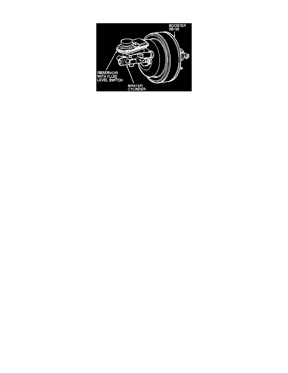
Fig. 2 Master Cylinder Reservoir & Brake Booster
The master cylinder reservoir, Fig. 2, is a clear translucent, plastic container with three main chambers. An integral fluid level switch is part of the
reservoir assembly, with one 3-pin electrical connector. A low pressure hose is attached to the reservoir which feeds brake fluid to the hydraulic control
unit reservoir. The reservoir and cap are serviced separately.