
Thunderbird V8-3.9L VIN A (2002)
18.
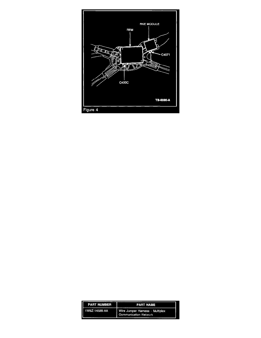
Locate and disconnect the RKE module electrical connector (Figure 4).
19.
Remove the connector secondary lock by gently lifting up on the lock located on the side of the connector with a small-standard size screwdriver.
20.
To remove the wire & terminal, insert a flat blade mini-screwdriver into the face of the connector and gently lift the locking tab inside the desired
cavity. Pull out the wire & terminal from rear of the connector. For detailed connector views, refer to Wiring Diagrams Manual, Section 150.
Immediately insert the matching wire from the service kit to avoid confusion. The following are the correct cavity/circuit locations:
a.
C4071 - Ckt 4-EG13 GY/OR, Cavity 3 - replace with GY/OR in Service Kit
b.
C4071 - Ckt 5-EG13 BU/BK, Cavity 4 - replace with BU/BK in Service Kit
21.
Reinstall the secondary locks in the RKE connector and reconnect to the RKE module. Use electrical tape to completely cover each of the 2 (two)
removed terminals.
22.
Locate and disconnect the 4th connector (C420c) at the REM (Figure 4).
23.
Remove the connector secondary lock by gently lifting up on the lock located on the side of the connector with a small-standard size screwdriver.
24.
To remove the wire & terminal, insert a flat blade mini-screwdriver into the face of the connector and gently lift the locking tab inside the desired
cavity. Pull out the wire & terminal from rear of the connector. For detailed connector views, refer to Wiring Diagrams Manual, Section 150.
Immediately insert the matching wire from the service kit to avoid confusion. The following are the correct cavity/circuit locations:
a.
C420c - Ckt 4-EG12 GY/WH, Cavity 1 - replace with GY/WH in Service Kit
b.
C420c - Ckt 5-EG12 BU/OR, Cavity 2 - replace with BU/OR in Service Kit
25.
Reinstall the secondary locks in the REM connector and reconnect to the REM. Use electrical tape to completely cover each of the 2 (two)
removed terminals.
26.
Starting at the Auxiliary Junction Box under the dash, secure the Service Wiring Harness to the main interior harness using electrical tape. Secure
the harnesses together at 6 inch intervals ending in the rear well area at the RKE module and REM. Install the 2nd (second) and 4th (fourth) screws
at the Left Door Sill Wiring Shield.
27.
Reinstall the RKE module/REM watershield and the vehicle interior trim panels in the reverse order that they were removed.
28.
Reconnect the battery and reset the Short Drop Window Calibration found in the Owner's Guide.