
Thunderbird V8-4.6L VIN W (1997)
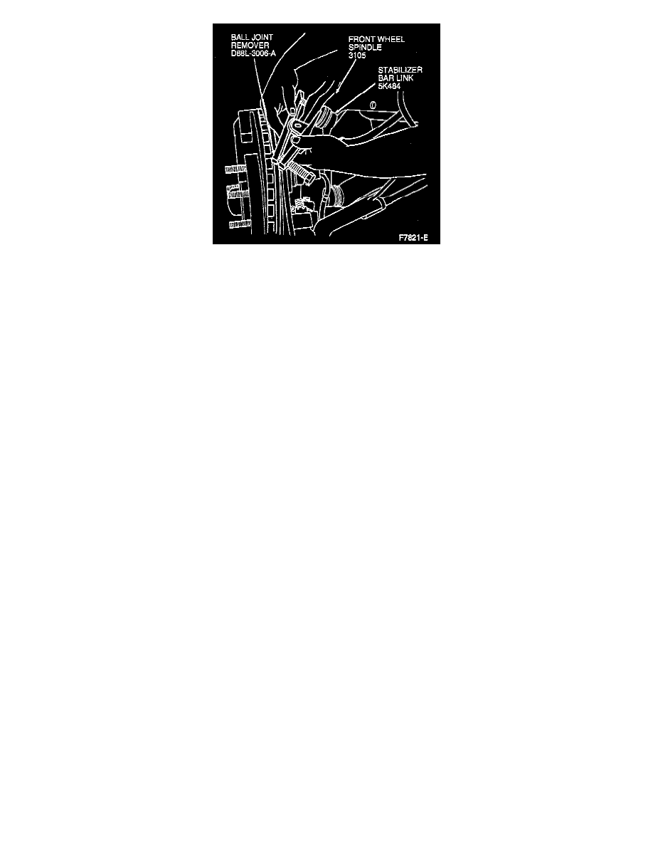
8. Remove stabilizer bar link at front wheel spindle using Ball Joint Remover D88L-3006-A or equivalent.
CAUTION: Use extreme care to avoid damage to the ball joint seal. If seal is damaged, replace the stabilizer bar link assembly.
9. Separate front suspension lower arm ball joint from front wheel spindle. Loosen nut and rap front wheel spindle with hammer. Remove nut and
discard.
10. Remove and discard upper front wheel spindle to upper front suspension arm ball joint bolt and nut. Spread slot slightly and remove front wheel
spindle from front suspension lower arm ball joint and vehicle.
INSTALLATION
1. Position front wheel spindle on front suspension lower arm and attach front suspension lower arm to front wheel spindle.
2. Install new nut on front suspension lower arm ball joint. Tighten to 113-153 Nm (84-112 ft. lbs.).
3. Assemble wheel spindle to upper arm ball joint. Install new nut and bolt. Tighten to 68-92 Nm (51-67 ft. lbs.).
3. Install wheel hub and bearing assembly. Tighten new front axle wheel hub retainer to 255-345 Nm (188-254 ft. lbs.). Install new front hub cap
grease seal.
4. Install front disc brake rotor and disc brake caliper assembly. See Brakes and Traction Control.
5. Install front brake anti-lock sensor. See Brakes and Traction Control.
6. Install stabilizer bar link to front wheel spindle. Tighten retaining nut to 40-55 Nm (30-40 ft. lbs.).
7. Attach tie rod end and nut. Tighten nut to 53-73 Nm (39-53 ft. lbs.). Continue to tighten until a slot in nut lines up with hole through stud. Install
new cotter pin.
8. Install tire and wheel assembly. Tighten lug nuts to 115-142 Nm (85-104 ft. lbs.). Do not use power tools, use torque wrench.