| Diagnosis and Testing Refer to Wiring Diagrams Section 303-06, for schematic and connector information. Inspection and Verification - Verify the customer concern.
- Visually inspect for obvious signs of electrical damage.
Visual Inspection Chart | Electrical | - Fuse(s)
- Wiring harness
- Electrical connector(s)
- Relay(s)
- Switch(es)
- Battery
- Starter motor
| - If an obvious cause for an observed or reported concern is found, correct the cause (if possible) before proceeding to the next step.
- If the cause is not visually evident, verify the symptom and refer to the Symptom Chart.
Symptom Chart | Symptom | Possible Sources | Action | | The engine does not crank but the relay clicks | * Battery | * REFER to: Charging System (414-00 Charging System - General Information, Diagnosis and Testing). | | * Circuit(s) * Starter relay * Starter motor | * | | The engine does not crank and the relay does not click | * Battery | * REFER to: Charging System (414-00 Charging System - General Information, Diagnosis and Testing). | | * Passive anti-theft system (PATS). | * REFER to: Anti-Theft - Passive (419-01B Anti-Theft - Passive, Diagnosis and Testing). | | * Circuit(s) * Starter relay * Ignition switch * Engine junction box (EJB) * Powertrain control module (PCM) | * | | The engine cranks slowly | * Battery | * REFER to: Charging System (414-00 Charging System - General Information, Diagnosis and Testing). | | * Starter motor * Battery cable(s) | * | | Unusual starter motor noise | * Starter motor. | * REMOVE the starter motor.
REFER to: Starter Motor - 2.2L Duratorq-TDCi (Puma) Diesel (303-06 Starting System, Removal and Installation) /
Starter Motor - 2.4L Duratorq-TDCi (Puma) Diesel/3.2L Duratorq-TDCi (Puma) Diesel (303-06 Starting System, Removal and Installation) /
Starter Motor - 2.3L Duratec-HE (MI4) (303-06 Starting System, Removal and Installation).
INSPECT the starter motor gear for damage. INSTALL a new starter motor as necessary. | | * Flywheel ring gear. | * Inspect the flywheel ring gear for damage. INSTALL a new flywheel ring gear as necessary. | | The starter spins but the engine does not crank | * Starter motor. | * REMOVE the starter motor.
REFER to: Starter Motor - 2.2L Duratorq-TDCi (Puma) Diesel (303-06 Starting System, Removal and Installation) /
Starter Motor - 2.4L Duratorq-TDCi (Puma) Diesel/3.2L Duratorq-TDCi (Puma) Diesel (303-06 Starting System, Removal and Installation) /
Starter Motor - 2.3L Duratec-HE (MI4) (303-06 Starting System, Removal and Installation).
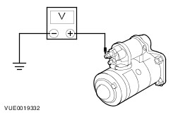
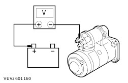
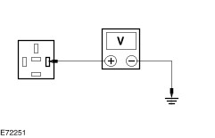
INSPECT the starter motor gear for damage. INSTALL a new starter motor as necessary. | | * Flywheel ring gear. | * Inspect the flywheel ring gear for damage. INSTALL a new flywheel ring gear as necessary. | Pinpoint Tests NOTE:Use a digital multimeter for all electrical measurements. | PINPOINT TEST A : THE ENGINE DOES NOT CRANK BUT THE RELAY CLICKS | | TEST CONDITIONS | DETAILS/RESULTS/ACTIONS | | A1: CHECK THE STARTER MOTOR SOLENOID FOR POWER | | | 1 Ignition switch in position III. | | | 2 Measure the voltage between the starter motor solenoid CDC35B circuit CBB17 (GN/RD) and ground. | | | Is the voltage greater than 10 volts? Yes No | | A2: CHECK CIRCUIT SBFD1A (RD) FOR VOLTAGE DROP | | | 1 Measure the voltage between starter motor solenoid CDC35C circuit SBFD1A (RD) and the battery positive terminal. | | | Is the voltage less than 2 volts? Yes CLEAN and TIGHTEN all battery positive cable connections. TEST the system for normal operation. If the concern persists, INSTALL a new starter motor.
REFER to: Starter Motor - 2.2L Duratorq-TDCi (Puma) Diesel (303-06 Starting System, Removal and Installation) /
Starter Motor - 2.4L Duratorq-TDCi (Puma) Diesel/3.2L Duratorq-TDCi (Puma) Diesel (303-06 Starting System, Removal and Installation) /
Starter Motor - 2.3L Duratec-HE (MI4) (303-06 Starting System, Removal and Installation).
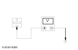
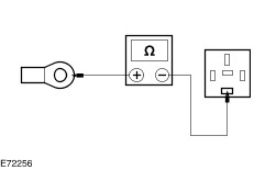
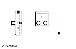
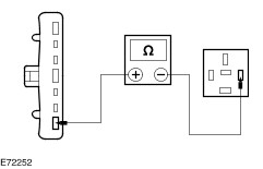
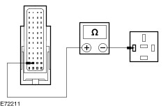
TEST the system for normal operation. No CLEAN and TIGHTEN all battery positive cables connections. TEST the system for normal operation. If the concern persists, INSTALL a new battery to starter motor solenoid cable. TEST the system for normal operation. | | A3: CHECK THE STARTER MOTOR SOLENOID POWER SUPPLY | | | 1 Ignition switch in position 0. | | | 2 Disconnect Starter Relay R4. | | | 3 Measure the voltage between the starter relay R4 connector pin 5 and ground. | | | Is the voltage greater than 10 volts? Yes No INSTALL a new EJB. TEST the system for normal operation. | | A4: CHECK CIRCUIT CBB17 (GN/RD) FOR OPEN CIRCUIT | | | 1 Ignition switch in position 0. | | | 2 Measure the resistance between the starter relay R4 connector, pin 5 and the starter motor solenoid CDC35B circuit CBB17 (GN/RD). | | | Is the resistance less than 1 ohm? Yes INSTALL a new starter relay. TEST the system for normal operation. If the concern persists, INSTALL a new starter motor.
REFER to: Starter Motor - 2.2L Duratorq-TDCi (Puma) Diesel (303-06 Starting System, Removal and Installation) /
Starter Motor - 2.4L Duratorq-TDCi (Puma) Diesel/3.2L Duratorq-TDCi (Puma) Diesel (303-06 Starting System, Removal and Installation) /
Starter Motor - 2.3L Duratec-HE (MI4) (303-06 Starting System, Removal and Installation).
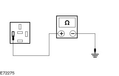
No REPAIR circuit CDC35 (GN/RD). TEST the system for correct operation. | | PINPOINT TEST B : THE ENGINE DOES NOT CRANK AND THE RELAY DOES NOT CLICK | | TEST CONDITIONS | DETAILS/RESULTS/ACTIONS | | B1: CHECK THE SWITCHED POWER TO THE STARTER RELAY | | | 1 Disconnect Starter Relay R4. | | | 2 Ignition switch in position III. | | | 3 Measure the voltage between the starter relay R4 pin 1, harness side and ground. | | | Is the voltage greater than 10 volts? Yes No | | B2: CHECK THE VOLTAGE TO THE IGNITION SWITCH | | | 1 Disconnect Ignition Switch CDC32. | | | 2 Measure the voltage between the ignition switch CDC32 pin 4, circuit SBP77 (RD/GY), harness side and ground. | | | Is the voltage greater than 10 volts? Yes No REPAIR circuit SBP77 (RD/GY). TEST the system for normal operation. | | B3: CHECK CIRCUIT CDC35 (BU/WH) FOR OPEN | | | 1 Measure the resistance between the ignition switch CDC32 pin 7, circuit CDC35 (BU/WH), harness side and the starter relay R4 pin 1, harness side. | | | Is the resistance less than 1 ohm? Yes No REPAIR the circuit. TEST the system for normal operation. | | B4: CHECK THE STARTER RELAY COIL FOR GROUND | | | 1 Measure the resistance between the starter relay R4 connector pin 2, circuit CDC12A and ground. | | | Is the resistance less than 1 ohm? Yes INSTALL a new starter relay. TEST the system for normal operation. No | | B5: CHECK CIRCUIT CDC12A (YE) FOR OPEN CIRCUIT | | | 1 Ignition switch in position 0. | | | 2 Disconnect PCM CE104B (2.2L/2.4L Duratorq-TDCi (Puma) Diesel Engines) . | | | 3 Disconnect PCM CE512B (2.3L Duratec-HE (MI4)). | | | 4 Measure the resistance between: - the starter relay R4 connector pin 2, circuit CDC12A (YE), harness side and the PCM CE104B pin L2, circuit CDC12A (YE), harness side (2.2L/2.4L Duratorq-TDCi (Puma) Diesel Engines) or
- the starter relay R4 connector pin 2, circuit CDC12A (YE), harness side and the PCM CE512B pin L2, circuit CDC12A (YE), harness side (2.3L Duratec-HE (MI4)).
| | | Is the resistance less than 1 ohm? Yes Using the WDS, CHECK for current DTCs. CORRECT all DTCs. TEST the system for normal operation. If the concern persists, INSTALL a new PCM.
REFER to: Powertrain Control Module (PCM) - Vehicles Without: PCM Security Shield (303-14 Electronic Engine Controls, Removal and Installation).
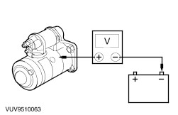
No REPAIR the circuit. TEST the system for normal operation. It the concern persists, INSTALL a new EJB | | PINPOINT TEST C : THE ENGINE CRANKS SLOWLY | | TEST CONDITIONS | DETAILS/RESULTS/ACTIONS | | C1: CHECK SBF01A (RD) FOR VOLTAGE DROP | | | 1 Ignition switch in position III. | | | 2 Measure the voltage between starter motor solenoid CDC35A circuit SBF01A (RD) and the battery positive terminal. | | | Is the voltage less than 0.5 volts? Yes No CLEAN and TIGHTEN all battery positive cables connections. TEST the system for normal operation. If the concern persists, INSTALL a new battery to starter motor solenoid cable. TEST the system for normal operation. | | C2: CHECK STARTER MOTOR FOR GROUND CONNECTION | | | 1 Ignition switch in position III. | | | 2 Measure the voltage between the starter motor housing and the battery negative terminal. | | | Is the voltage less than 0.5 volts? Yes INSTALL a new starter motor.
REFER to: Starter Motor - 2.2L Duratorq-TDCi (Puma) Diesel (303-06 Starting System, Removal and Installation) /
Starter Motor - 2.4L Duratorq-TDCi (Puma) Diesel/3.2L Duratorq-TDCi (Puma) Diesel (303-06 Starting System, Removal and Installation) /
Starter Motor - 2.3L Duratec-HE (MI4) (303-06 Starting System, Removal and Installation).
TEST the system for normal operation. No CLEAN and TIGHTEN all battery negative cable connections, starter motor mounting and body to ground straps. TEST the system for normal operation. If the concern persists, INSTALL a new battery negative cable. TEST the system for normal operation. | |