
Transit Connect L4-2.0L (2010)
-
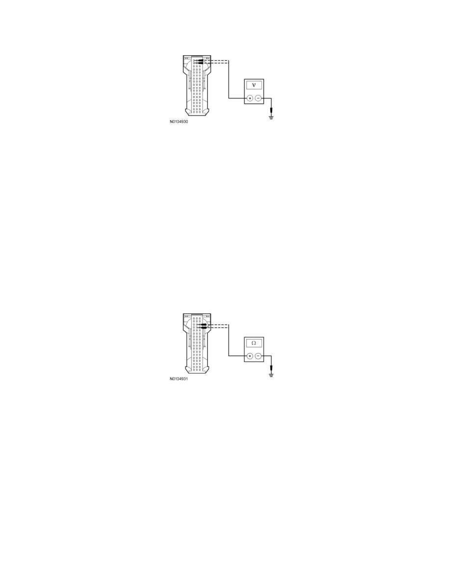
Disconnect: SRM C2307.
-
Measure the voltage between the SRM C2307-17, circuit 29-MC12 (OG/YE), harness side and ground; and between the SRM C2307-18, circuit
29-MC12 (OG/YE), harness side and ground.
-
Is the voltage greater than 10 volts?
Yes
GO to F2.
No
VERIFY the Central Junction Box (CJB) fuse 151 (15A) is OK. If OK, REPAIR the circuit. If not OK, REFER to the Wiring Diagrams to identify the
possible causes of the circuit short. CLEAR the DTCs. REPEAT the network test with the scan tool. See: Diagrams/Electrical Diagrams/Diagrams By
Number
-------------------------------------------------
F2 CHECK THE SRM GROUND CIRCUIT FOR AN OPEN
-
Disconnect: Negative Battery Cable.
-
Measure the resistance between the SRM C2307-33, circuit 91-MC12 (BK/YE), harness side and ground; and between the SRM C2307-34, circuit
91-MC12 (BK/YE), harness side and ground.
-
Is the resistance less than 5 ohms?
Yes
GO to F3.
No
REPAIR the circuit. CONNECT the negative battery cable. CLEAR the DTCs. REPEAT the network test with the scan tool.
-------------------------------------------------
F3 CHECK THE MS-CAN CIRCUITS BETWEEN THE SRM AND THE DLC FOR AN OPEN
-
Measure the resistance between the SRM C2307-14, circuit 4-EC1 (GY/RD), harness side and the DLC C251-3, circuit 4-EC1 (GY/RD)/4-EC13
(GY/VT)/4-EC14 (GY/OG), harness side.