
Transit Connect L4-2.0L (2010)
-------------------------------------------------
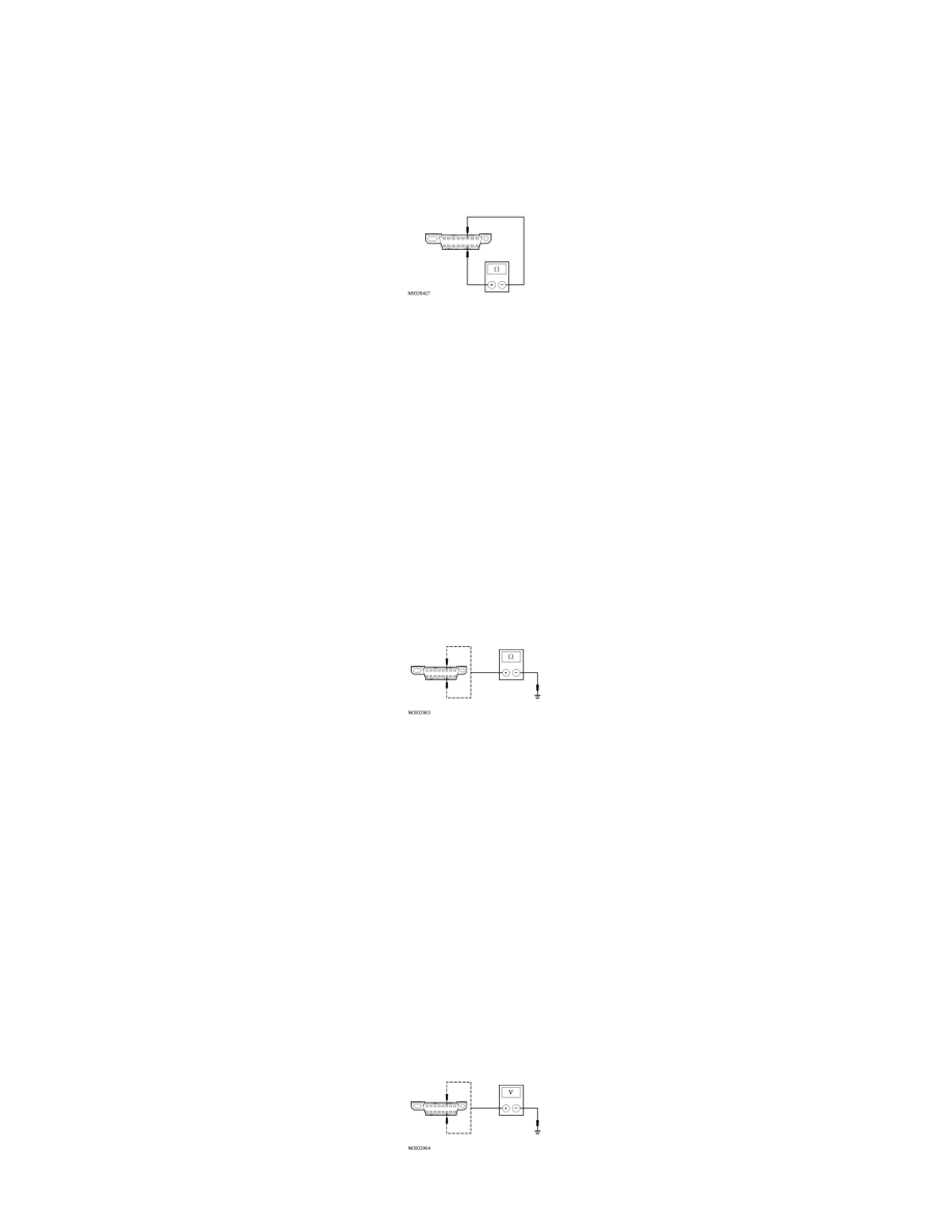
M2 CHECK THE HS-CAN TERMINATION RESISTANCE
-
Disconnect: Negative Battery Cable.
-
Measure the resistance between the DLC C251-6, circuit 4-EC7 (GY/RD)/4-EC8 (GY/VT), harness side and the DLC C251-14, circuit 5-EC7
(BU/RD)/5-EC8 (BU/WH), harness side.
-
Is the resistance between 54 and 66 ohms?
Yes
GO to M3.
No
GO to M5.
-------------------------------------------------
M3 CHECK THE HS-CAN (+) AND HS-CAN (-) CIRCUITS FOR A SHORT TO GROUND
-
Measure the resistance between the DLC C251-6, circuit 4-EC7 (GY/RD)/4-EC8 (GY/VT), harness side and ground; and between the DLC
C251-14, circuit 5-EC7 (BU/RD)/5-EC8 (BU/WH), harness side and ground.
-
Are the resistances greater than 1,000 ohms?
Yes
CONNECT the negative battery cable. GO to M4.
No
GO to M15.
-------------------------------------------------
M4 CHECK THE HS-CAN (+) AND HS-CAN (-) CIRCUITS FOR A SHORT TO VOLTAGE
-
Ignition ON.
-
Measure the voltage between the DLC C251-6, circuit 4-EC7 (GY/RD)/4-EC8 (GY/VT), harness side and ground; and between the DLC
C251-14, circuit 5-EC7 (BU/RD)/5-EC8 (BU/WH), harness side and ground.
-
Is the voltage greater than 6 volts?