
Windstar V6-232 3.8L (1995)
Installation
NOTE: Lightly oil all retaining bolt and stud bolt threads before installation.
NOTE: When using silicone rubber sealer, assembly must occur within 15 minutes after sealer application. After this time, the sealer may start to
setup, and its sealing effectiveness may be reduced.
1. The lower intake manifold, cylinder head, and cylinder block mating surfaces should be clean and free of old gasketing material. Use a suitable
solvent to clean these surfaces.
2. If intake manifold was disassembled:
-
Apply a coat of Pipe Sealant with Teflon® D8AZ-19554-A or equivalent meeting Ford specification WSK-M2G350-AZl2A to the threads of
the water temperature indicator sender unit, all vacuum fillings, hot water heater elbow connections, engine coolant temperature sensor and
electrical fillings, if equipped. Tighten water temperature indicator sender unit to 12-16 Nm (9-12 lb-ft) and tighten engine coolant
temperature sensor to 14-19 Nm (10-14 lb-ft).
-
Install water thermostat (note direction) and water hose connection . Install water hose connection Tighten retaining bolts to 20-30 Nm (15-22
lb-ft).
3. Apply Gasket and Trim Adhesive D7AZ-19B508-B or equivalent meeting Ford specification ESE-M2G52-A to each cylinder head mating
surface. Press new intake manifold gaskets into place, using locating pins as necessary to aid in assembly.
NOTE: Using solvent, clean sealing surfaces of cylinder heads and intake manifold before applying silicone rubber.
4. Apply a 3-4mm (1/8-inch) bead of Silicone Rubber D6AZ-19562-BA or equivalent meeting Ford specifications ESB-M4G92-A and
ESE-M4G195-A at each corner where the cylinder head joins the cylinder block.
5. Install front and rear intake manifold end seals.
6. Carefully install intake manifold into position on cylinder block and cylinder heads. Use locating pins as necessary to guide intake manifold.
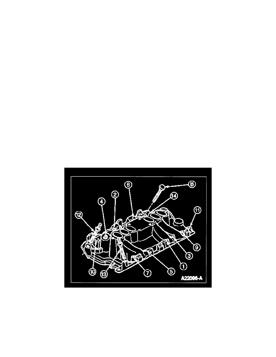
7. Install bolts in their original locations. Tighten in numerical sequence as shown in the following illustration to the following specifications in two
steps:
a. 18Nm (13 lb-ft)
b. 22Nm (16 lb-ft)
8. Connect engine control sensor wiring to water temperature indicator sender unit and engine coolant temperature sensor.
9. Position front intake manifold support to lower intake manifold and install nut. Tighten nut to 20-30 Nm (15-22 lb-ft).
10. Install fuel injectors and fuel injection supply manifold.
11. Install bolt and nut securing coil bracket to lower intake manifold . Tighten bolt and nut to 20-30 Nm (15-22 lb-ft).
12. Position rear intake manifold support behind fuel rail assembly bracket and to camshaft sprocket. Tighten bolt to 20-30 Nm (15-22 lb-ft).
13. Position power steering line bracket to coil bracket and install retaining bolt. Tighten bolt securely.
14. Install heater water hose.
15. Connect water bypass hose to lower intake manifold.
16. Connect upper radiator hose to water outlet connection.
17. Install upper intake manifold.