
Windstar V6-232 3.8L (1995)
Compressor Clutch: Description and Operation
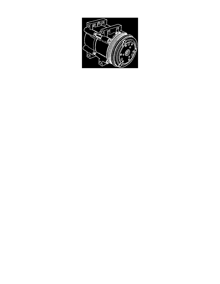
The FS-10 A/C compressor has the following characteristics:
-
The FS-10 is a swashplate-design, 10-cylinder aluminum A/C compressor using the tangential design mount.
-
Displacement of 170 cc (10.4 cubic inches).
-
Lubricated by a charge of Motorcraft YN-12b refrigerant oil or equivalent meeting Ford specification WSH-M1C231-B in the refrigerant system.
-
A one-piece lip-type seal (replaceable from the front of the A/C compressor) is used to seal it at the shaft opening in the assembly.
-
Five double-acting pistons, positioned axially around the compressor shaft, operate within the cylinder assembly. The pistons are started by a
swashplate that is pressed on the compressor shaft.
-
The swashplate changes the rotating action of the shaft to provide a reciprocating force to each of the five pistons. This driving force is applied,
through shoes, to the midpoint of each of the double-end pistons.
-
Reed-type discharge valves are assembled on the valve plate.
-
The valve plate is located with the suction reed valve between the cylinder assembly and the head at each end of the A/C compressor.
-
The heads are connected to each other by gas-tight passageways through the cylinder assembly which direct the refrigerant gas to the suction and
discharge ports located in the rear head.
The magnetic A/C clutch has the following characteristics:
-
It drives the compressor shaft.
-
When battery positive voltage (B+) is applied to the A/C clutch field coil, the clutch plate and hub assembly (which is solidly coupled to the
compressor shaft) is drawn rearward by magnetic force toward the A/C clutch pulley which rotates freely on the compressor front head casting.
-
The magnetic force locks the clutch plate and hub assembly and the A/C clutch pulley together as one unit.
-
The clutch plate and hub assembly then turns the A/C clutch pulley causing the compressor shaft to rotate.
-
When B+ is removed from the A/C clutch field coil, springs in the clutch plate and hub assembly move the clutch plate away from the A/C clutch
pulley.
-
The clutch plate and hub assembly and compressor shaft stop rotating.