
Windstar V6-232 3.8L (1995)
Transmission Range Sensor: Initial Inspection and Diagnostic Overview
Inspection and Verification
1. Visually inspect the system components for customer's concern.
2. Verify wiring and connections for the transmission range sensor to find looseness, corrosion damage or other obvious causes for a malfunction.
3. If an obvious cause for an observed or reported malfunction is found, correct the cause if possible before proceeding to the next step.
4. If the cause of the malfunction cannot be found by system inspection, refer to Symptom Chart which serves as a guide for further diagnosis to
validate customer's concern. See: Symptom Related Diagnostic Procedures
Important Information
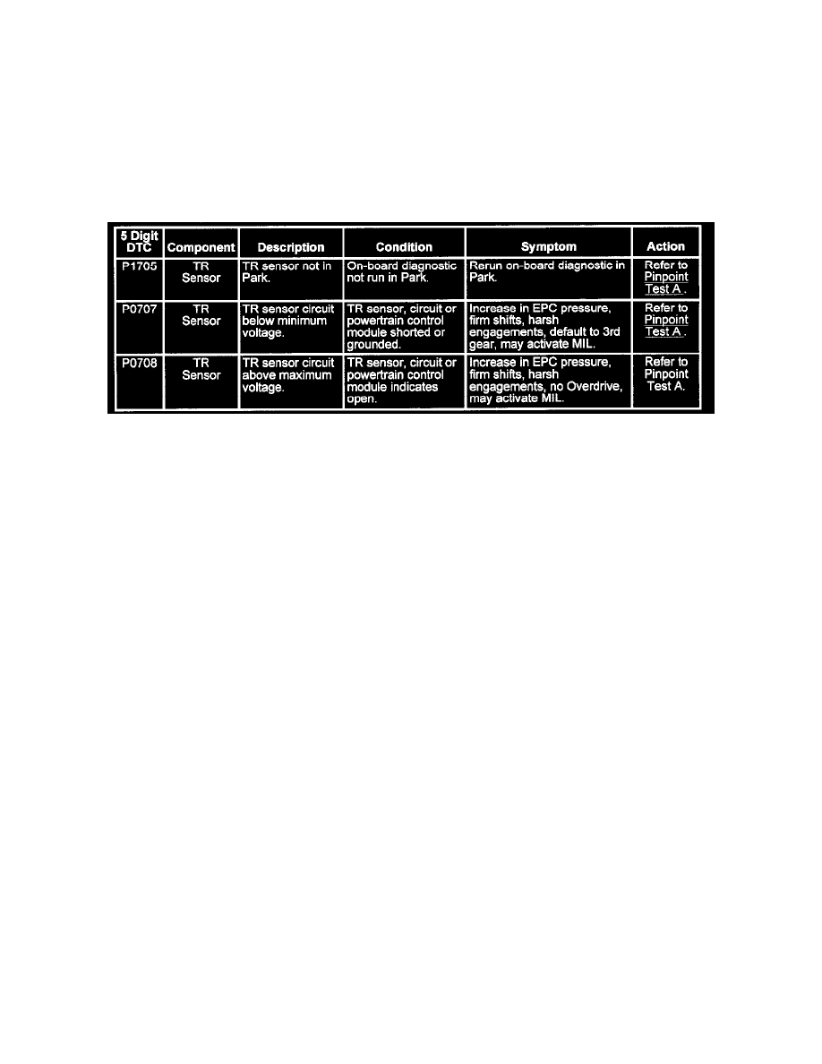
On-Board Diagnostic Trouble Code Description Chart
If DTCs are present while performing the On-Board Diagnostic, refer to the On-Board Diagnostic Trouble Code Description Chart for the appropriate
service procedure.
Note:
-
Prior to beginning Pinpoint Tests, refer to any TSBs for transaxle concerns.
-
Prior to beginning Pinpoint Tests, the vehicle harness must be checked for continuity and shorts; the powertrain control module (PCM) (12A650)
must be checked for any concerns.
-
If any non-transaxle DTCs appear, service those codes first.
They could affect the electrical operation of the transaxle.
Record and erase codes from continuous memory after service has been performed.
After servicing any DTCs in the Quick Test, the Quick Test should be repeated.
-
Check the powertrain control module wiring harness for proper connections, bent or broken pins, corrosion, loose wires, proper routing, proper
seals and their condition.
Check the powertrain control module, sensors and actuators for physical damage.