
Windstar V6-232 3.8L (1995)
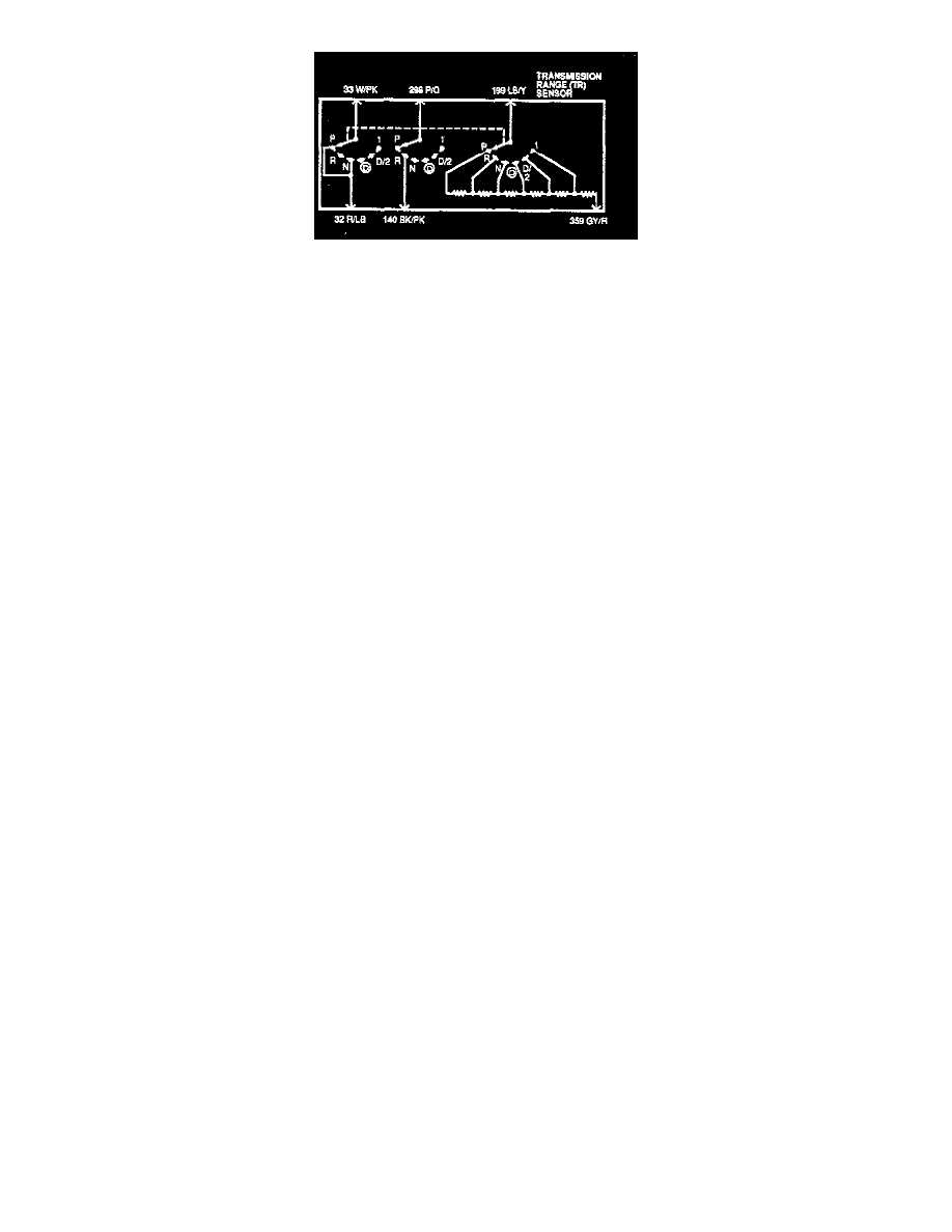
Refer to the schematic and charts when performing the Pinpoint Test Steps.
Tests
A1 AX4S Electronic Diagnostics
-
Check to make sure transmission range sensor harness connector is fully seated, terminals are fully engaged in connector and in good condition
before proceeding.
-
Verify shift linkage adjustment in the Overdrive position.
-
Turn ignition switch OFF.
-
Apply parking brake control.
-
Place transaxle in Neutral.
-
Verify that Transmission Range/Manual Lever Position Sensor Alignment Tool T92P-70010-AH fits in the appropriate slots.
Is the transmission range sensor properly adjusted?
Yes
REMOVE tool.
GO to A2.
No
ADJUST transmission range sensor. See: Adjustments
After adjustments, PLACE shift control selector lever in Park.
CLEAR DTC and verify repair.
A2 Check Electrical Signal Operation
-
Turn ignition switch OFF.
-
Disconnect transaxle connector.
CAUTION: DO NOT pry on connector. Pull up on vehicle harness connector.
-
Using a mirror, inspect both ends of the connector for damaged or pushed-out pins, corrosion, loose wires and missing or damaged seals.
Note: Refer to the schematic and chart preceding this pinpoint test. See: Description
-
Connect a VOM positive test lead to TR circuit and negative test lead to Signal Return (SIG RTN) circuit of transaxle harness connector.
-
Place VOM on 20 volt scale.
-
Turn ignition switch to RUN, engine OFF.
Is voltage between 4.75 and 5.25 volts?
Yes
GO to A3.
No
REFER to Computers and Controls/System Diagnosis for diagnosis of NO Reference Voltage, Pinpoint Test TD.
A3 Check Continuity Of TR Sensor Harness Circuits
-
Turn ignition switch to OFF.
CAUTION: Do not pry connector. Press button and pull up on vehicle harness.
-
Disconnect transmission range sensor.
-
Inspect for damaged or pushed-out pins, corrosion, or loose wires.
-
Install Rotunda Breakout Box or equivalent. Leave powertrain control module disconnected.
-
Inspect disconnected powertrain control module for damaged or pushed-out pins, corrosion, or loose wires.
Note: Refer to the schematics and charts preceding this pinpoint test. See: Description
-
Measure resistance between powertrain control module test Pin 91 at breakout box and SIG RTN circuit at TR sensor vehicle harness connector.