
Windstar V6-232 3.8L (1995)
Driveshaft & Joint Assembly
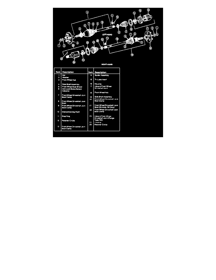
DISASSEMBLY
1. Remove driveshaft and joint assembly from vehicle.
2. Cut and remove both driveshaft joint boot clamps, then slide housing off spider assembly.
3. Check driveshaft joint boot grease for contamination if replacing boot by rubbing between two fingers. A gritty feeling indicates grease
contamination. If grease appears contaminated, proceed with complete CV joint disassembly and inspection. If driveshaft joint is operating
satisfactorily and grease does not appear to be contaminated, replace only grease and driveshaft joint boot.
4. Slide driveshaft joint boot back on interconnecting shaft, then move stop ring back on interconnecting shaft using suitable snap ring pliers.
5. Move spider assembly back on interconnecting shaft to allow access to retainer circlip, then remove circlip from interconnecting shaft. Retainer
circlip must not be reused. Replace with new circlip before assembly.
6. Remove spider assembly from interconnecting shaft, then the stop ring and slide driveshaft boot off interconnecting shaft. Remove tri-lobe insert
from lefthand inboard CV (plunge) joint housing. Remove grease from housing, spider assembly and driveshaft joint boot.
7. Inspect spider assembly and housing for excessive wear, looseness, pitting, rust or other damage.
ASSEMBLY
NOTE: Tighten driveshaft joint boot clamp securely, but not to the point where the clamp bridge is cut or the driveshaft joint boot is damaged.
1. Install driveshaft joint boot clamp and boot on interconnecting shaft, noting the following:
a. Ensure boot is seated in boot groove on interconnecting shaft.
b. Position boot over boot end and locate clamp tabs in slots while tightening clamp by hand.
2. Install stop ring in groove on interconnecting shaft, then install new retainer circlip (supplied with service kit) in groove nearest end of
interconnecting shaft, noting the following:
a. Do not reuse retainer circlip. Replace retainer circlips before assembly.
b. Do not overexpand or twist retainer circlip during installation.
c. Install retainer circlip by starting one end in groove and working circlip over inboard CV joint stub shaft housing end and into groove. This
will avoid overexpanding circlip.
3. Install spider assembly on interconnecting shaft with chamfered side toward stop ring. Spider assembly is fully seated on interconnecting shaft
when "click" is heard, indicating snap ring engagement.
4. On lefthand inboard front wheel driveshaft joint, install tri-lobe insert on housing.
5. On both driveshaft joints, fill housing with grease supplied in service kit, then spread remaining grease evenly inside front wheel driveshaft joint